
Indication change instrument cluster

a technology of instrument cluster and illumination, applied in the direction of simultaneous indication of multiple variables, instruments, transportation and packaging, etc., can solve the problems of requiring a significant amount of packaging space and expensive vehicles with a significant number of gauges, and achieve the effect of more compact and cost-effective instrument cluster configuration

Inactive Publication Date: 2009-11-03
CONTINENTAL AUTOMOTIVE SYST INC
View PDF8 Cites 5 Cited by
  • Summary
  • Abstract
  • Description
  • Claims
  • Application Information

AI Technical Summary

Benefits of technology

This configuration reduces costs and packaging space while maintaining the ability to display multiple types of vehicle information, offering a more efficient and cost-effective instrument cluster solution.

Problems solved by technology

This can be expensive for vehicles with a significant number of gauges.
Further, this traditional configuration requires a significant amount of packaging space within a dashboard to mount the instrument cluster.

Method used


Image

  • Indication change instrument cluster
  • Indication change instrument cluster
  • Indication change instrument cluster

Examples


Embodiment Construction

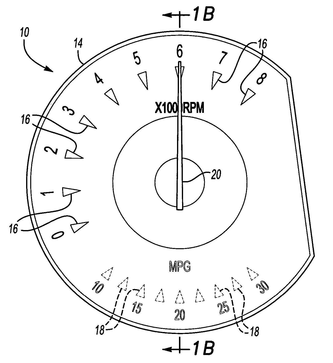
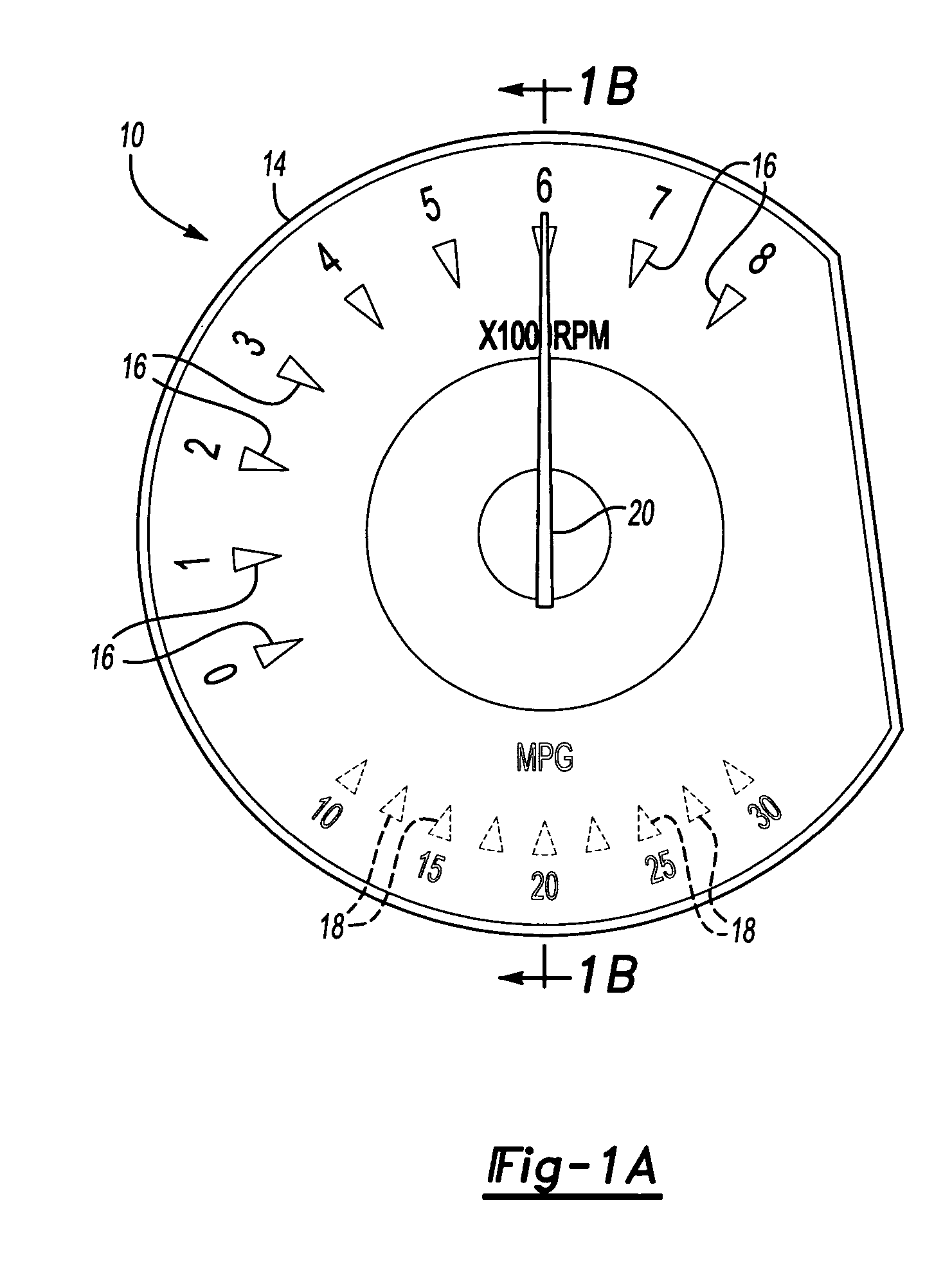
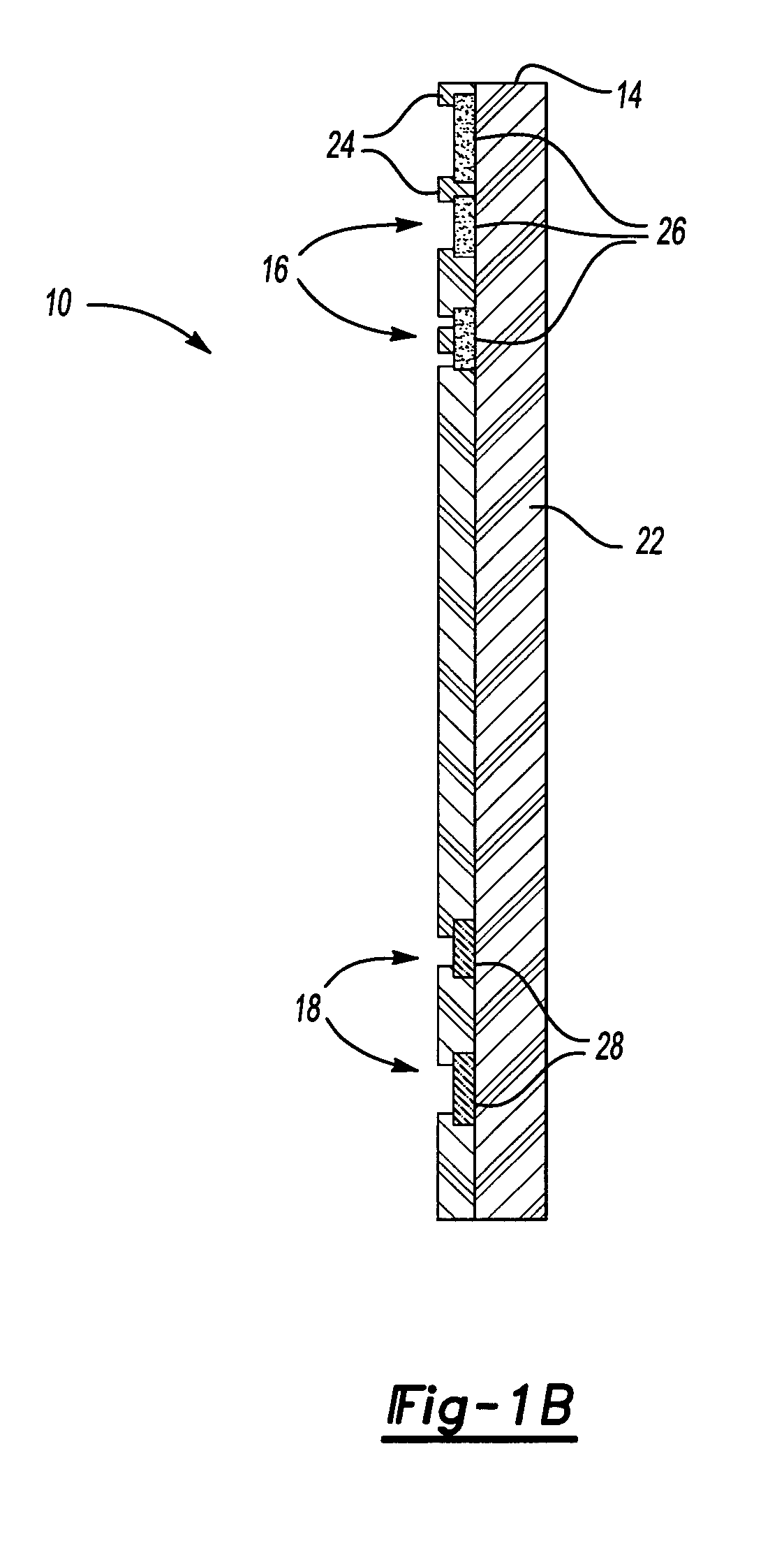
[0022]FIG. 1A shows an illuminated gauge 10 for an instrument cluster 12 (FIGS. 4A-4B) that is mounted within a vehicle dashboard (not shown). The illuminated gauge 10 includes a single dial 14 that includes a first range of markings 16 to identify a first type of vehicle information and a second range of markings 18 to identify a second type of vehicle information that is different from the first type. A common pointer 20 is selectively controlled to operate in either the first range of markings 16 or the second range of markings 18. In the example of FIG. 1A, the first range of markings 16 comprise markings that indicate a range of engine revolutions per minute (RPM), and the second range of markings 18 comprise markings that indicate fuel economy information, such as miles-per-gallon (MPG).

[0023]As shown in FIG. 1B, the dial 14 includes a body portion 22 made from polycarbonate (PC) material or polymethyl methacrylate (PMMA) material, for example. The first 16 and second 18 range...


PUM


Abstract

An illuminated gauge includes a dial with at least first and second ranges of markings. The first range of markings indicates one type of vehicle information and the second range of markings indicates another type of vehicle information. A single motor is used to move a common pointer between the first and second ranges of markings. A selector is to be operated by a user to select between the different types of vehicle information.

Description

CROSS REFERENCE TO RELATED APPLICATION[0001]The application claims priority to U.S. Provisional Application No. 60 / 729,023 which was filed on Oct. 21, 2005.BACKGROUND OF THE INVENTION[0002]This invention generally relates to illuminated gauge dials. More particularly, this invention relates to a gauge dial that can display at least two different types of vehicle information with a common pointer.[0003]Vehicles include instrument panels with illuminated gauges and pointers to indicate vehicle information such as speed, fuel economy, oil pressure, voltage, etc. An illuminated gauge is comprised of a dial with associated vehicle information, a light source and light housing, and a pointer that is driven by a motor for movement relative to the dial. The dial includes markings with a specified range of information, and the motor positions the pointer to indicate the appropriate marking within the range of information.[0004]In a typical arrangement, each gauge includes one type of vehicle...

Claims


Application Information

Patent Timeline
Patent Type & Authority Patents(United States)
IPC IPC(8): G08B21/00
CPCB60K35/00B60K37/02G01D7/08G01D13/265G01P1/07G01D7/02B60K2350/1064B60K2350/901G01D2213/20B60K35/60B60K35/215B60K2360/6992B60K35/654
Inventor TAKATO, KENICHI
Owner CONTINENTAL AUTOMOTIVE SYST INC
Learn More