Rotatable thermostat

a technology of rotating thermostats and thermostats, which is applied in the field of rotating thermostats, can solve the problems of inconvenient inability to fit into recently vacated space, and inability to meet the needs of users, etc., and achieve the effect of convenient and inexpensive replacement of thermostats

Active Publication Date: 2009-11-10
RANCO OF DELAWARE +1
View PDF34 Cites 148 Cited by
  • Summary
  • Abstract
  • Description
  • Claims
  • Application Information

AI Technical Summary

Benefits of technology

[0012]In view of the above, the present invention provides a new and improved thermostat that overcomes one or more problems existing in the art. More particularly, the present invention provides a new and improved thermostat that is adaptable to fit within an existing space vacated by a previously used thermostat. Even more particularly, the present invention provides a new and improved thermostat that is able to conveniently and inexpensively cover the footprint of the previously used thermostat without the need for a wall plate, new wallpaper, new paint, and / or new trim. Still more particularly, the present invention provides a new and improved thermostat that is configurable to orient the user interface and the display for use by either right or left handed users.

Problems solved by technology

As one thermostat becomes obsolete and / or outdated, that unwanted thermostat is often replaced with another thermostat.
Unfortunately, when one thermostat is replaced with another, property owners and tenants are discovering that the replacement thermostat does not always fit into the space recently vacated by the previous thermostat.
If using an alternate style of thermostat is not an option, the existing space may have to somehow be expanded.
Each of these remedies will undesirably add both time and expense to the process of replacing one thermostat with another.
In addition to the above, property owners and tenants are also finding that a replacement thermostat may not cover the same portion of the wall as the old thermostat when mounted.
In such cases, an unsightly halo (e.g., a ring or pane of discolored paint or wallpaper) is exposed on the surface of the wall where the previous thermostat had been mounted.
However, if such a wall plate is not available or is simply an unacceptable method of concealing the halo, the property owner or tenant may have to replace wallpaper, apply new paint to all or a portion of the wall, add new trim, and the like.
Again, each of these solutions will undesirably add both time and expense to the process of replacing one thermostat with another.
Unfortunately, to provide the information to the user in a proper orientation based on the mounting configuration, the user is required to separate the thermostat housing from the mounting plate and manipulate an electrical jumper located in the controller of the thermostat.
However, many consumers are unfamiliar with electronics and are uncomfortable rewiring the controller of the thermostat with an electrical jumper.
Further, if the rewiring is not done correctly, the display is not likely to be correct.
Also, if the jumper is not seated firmly in place, the connection may become intermittent, which could result in an erroneous display orientation.
A further problem may also be realized when the occupant or user who is left handed replaces such a round analog thermostat with a new digital thermostat.
While this allows a right handed user to adjust the thermostat via the user interface and still see the display, a left handed user tends to obstruct the display as they are required to reach across the display to manipulate the user interface.
Alternatively, the user is forced to manipulate the user interface with their right hand, which is not comfortable or natural for the left-handed user.
These issues tend to detract from the user experience with the new thermostat and may result in product returns.
Unfortunately, the previously discussed thermostats that allow for mounting in two different configurations also includes labeling on the housing itself to identify the function of certain buttons, switches, etc. of the thermostat.
As a result, mounting the thermostat in any other orientation, such to allow a left handed user to use the thermostat, will result in the labeling being upside down.

Method used


Image

  • Rotatable thermostat
  • Rotatable thermostat
  • Rotatable thermostat

Examples


Embodiment Construction

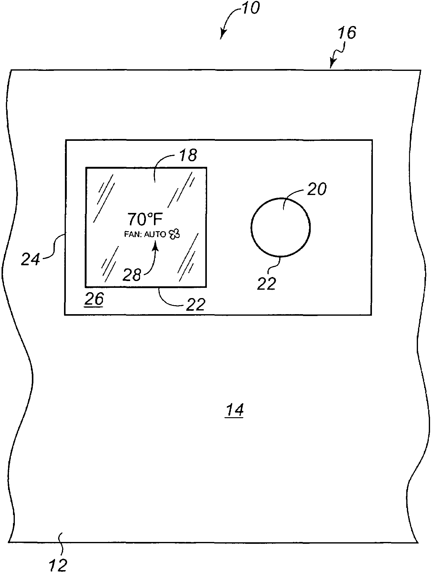
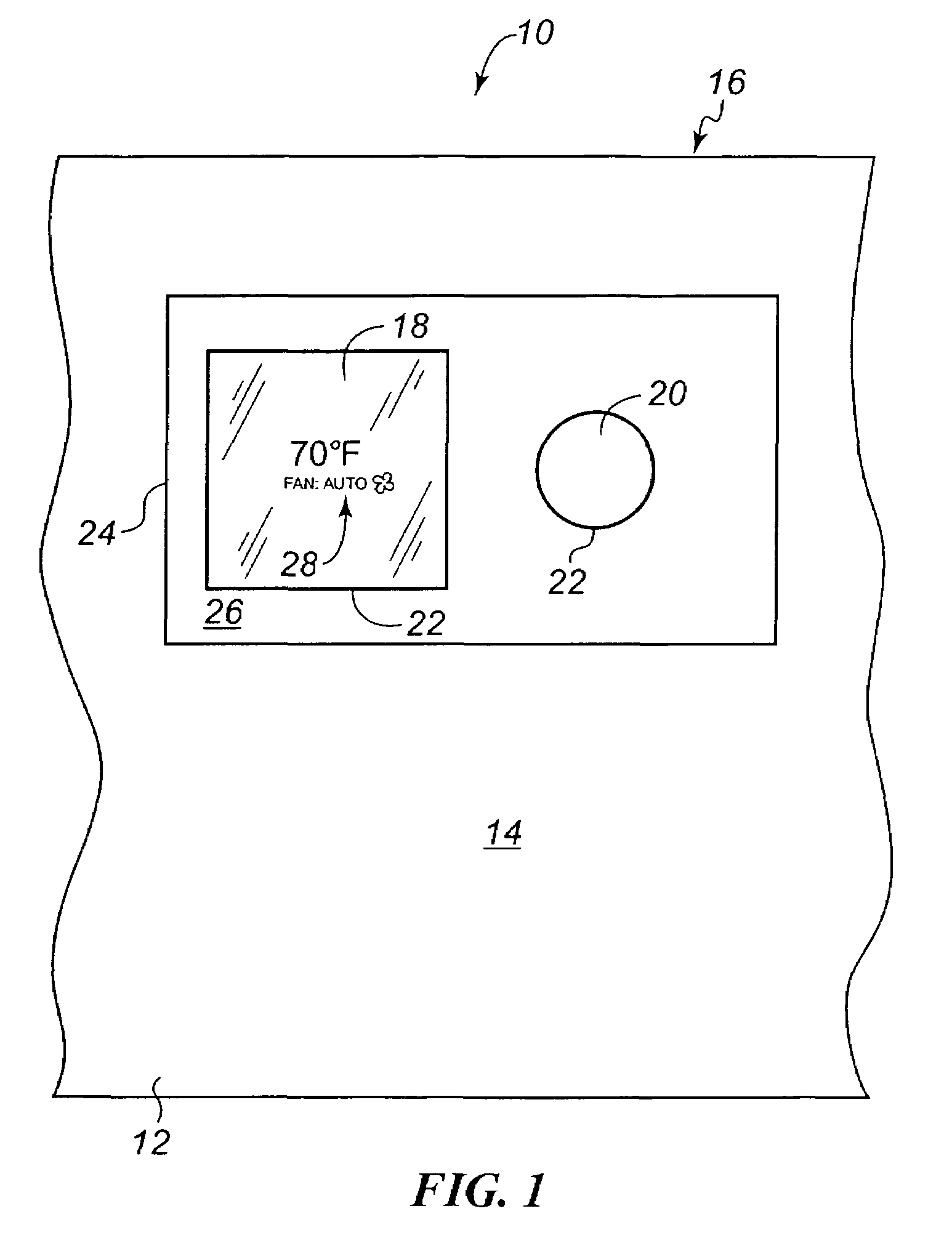
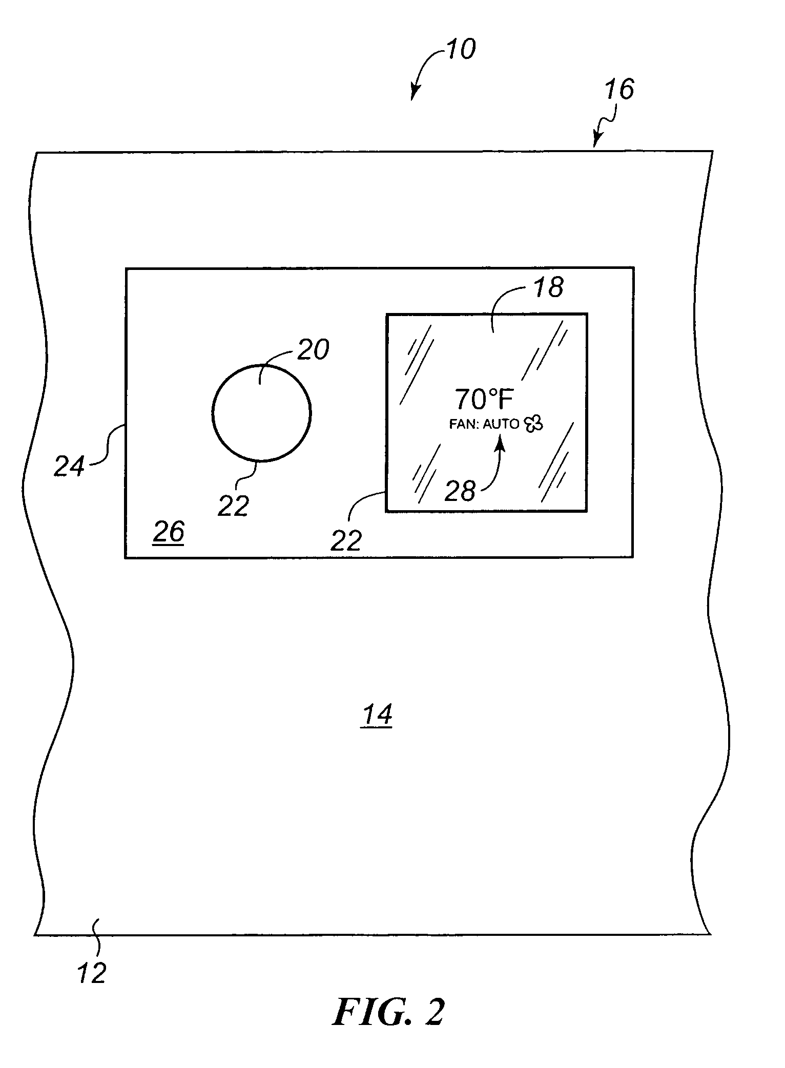
[0023]Referring to FIG. 1, an embodiment of a temperature control device, such as thermostat 10, constructed in accordance with the teachings of the present invention is shown. As described above, such a thermostat 10 is often mounted to a wall 12 whose outer surface 14 has previously been painted and / or wallpapered around an older mechanical thermostat. In such a situation, as will be described more fully below, the thermostat 10 needs to cover the prior area of the old thermostat. The thermostat 10 of the present invention is particularly suited for such applications. However, one skilled in the art will recognize from the following description that such a thermostat 10 may also or alternatively be installed initially in new construction, and in such installations additional advantages will become apparent.

[0024]The thermostat 10 includes a housing 16, a user interface device, e.g. display 18, and a user input device 20. The housing 16 generally includes or interfaces with mountin...


PUM


Abstract

A thermostat that can display information in multiple different orientations is provided. The thermostat includes a housing, a display, and an input device. As the housing is mounted in a particular orientation, the thermostat changes the orientation of the information for properly displaying same to a user. This is accomplished by sensing the orientation of the housing in one embodiment, and through user selection of a desired orientation in another embodiment. A separate display and input device(s) are provided in one embodiment, and a combined touch screen display and input device is provided in another embodiment.

Description

FIELD OF THE INVENTION[0001]This invention generally relates to heating, ventilation, and air conditioning systems and, more particularly, to thermostats employed in those systems.BACKGROUND OF THE INVENTION[0002]Occupants of dwellings and commercial structures have long benefited from the inclusion of a heating, ventilating, and air conditioning (HVAC) system that regulates the temperature and humidity within the dwelling or structure. Traditionally, a thermostat that controlled this temperature regulating equipment was a fairly simple electromechanical device wired to a heating device and / or to a cooling device. Once installed, the user need only move a selector switch between heating and cooling to designate which equipment was desired to be operated, move a selector switch between run and auto for a fan control, and rotate a dial to a desired set point temperature. No other user interface to the basic thermostat was needed or available.[0003]Advances in control electronics have ...

Claims


Application Information

Patent Timeline
Patent Type & Authority Patents(United States)
IPC IPC(8): G05D23/00
CPCF24D19/10G05D23/1902G09F9/35G09F9/30
Inventor CHAPMAN, JR., JOHN GILMANCATLIN, GEORGE N.ASHWORTH, NICHOLASBURT, ROBERT
Owner RANCO OF DELAWARE
Why Eureka
Try Eureka