System for controlling fluid flow to an appliance

a technology for controlling fluid flow and inline appliances, which is applied in the direction of fluid heaters, lighting and heating apparatus, heating types, etc., can solve the problems of inability to allow full fluid flow, cumbersome installation in limited spaces, and large design size, and achieves convenient cleaning and flushing

Active Publication Date: 2009-11-24
NIBCO INC
View PDF4 Cites 21 Cited by
  • Summary
  • Abstract
  • Description
  • Claims
  • Application Information

AI Technical Summary

Benefits of technology

[0005]Advantageously, the fluid isolation according to the invention allows testing of an installed in-line appliance and easy cleaning and flushing of any such in-line appliance.

Problems solved by technology

Unfortunately, however, current designs are large and bulky and do not allow for a full fluid flow.
This is undesirable for many reasons.
In-line appliances are typically disposed in limited spaces, thus the large bulky size of current designs make them cumbersome and difficult to install in limited spaces.
In some cases the limited space makes them impossible to install, remove and / or repair.
Disadvantageously, the partial fluid flow capability of current designs makes it difficult for the in-line appliance to be accurately tested.

Method used


Image

  • System for controlling fluid flow to an appliance
  • System for controlling fluid flow to an appliance
  • System for controlling fluid flow to an appliance

Examples


Embodiment Construction

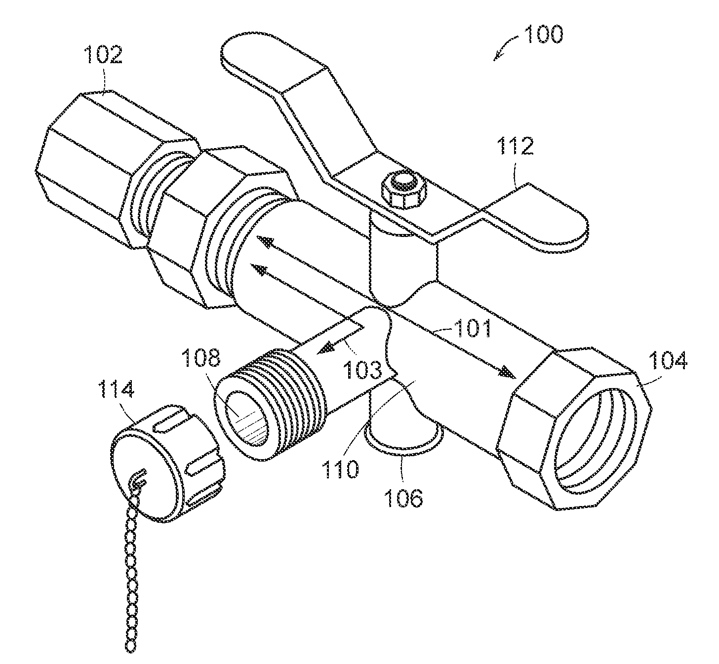
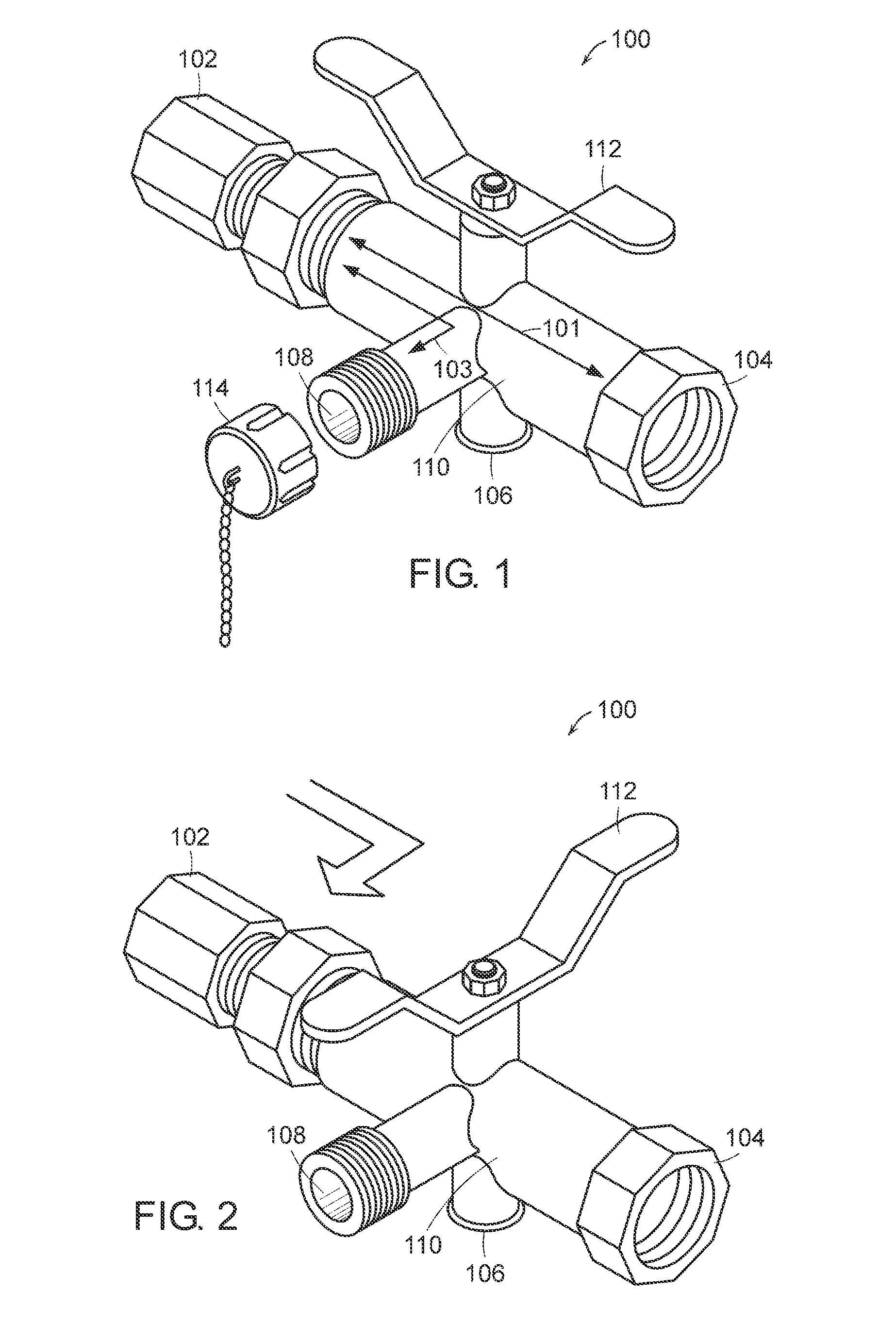
[0016]Referring to FIG. 1, a hot water isolation valve 100 is shown and includes a first hot water port 102, a second hot water port 104, a hot water relief port 106 and a hot water drain port 108. Hot water isolation valve 100 defines a hot water flow channel 101 and a hot water drain channel 103. The hot water flow channel 101 provides fluid communication between the first hot water port 102 and the second hot water port 104. The hot water drain channel 103 provides fluid communication between the first hot water port 102 and the hot water drain port 108. The hot water isolation valve 100 includes a flow diversion device (not shown), such as a ball valve, disposed within a valve portion 110 disposed between first hot water port 102, second hot water port 104, hot water relief port 106 and hot water drain port 108. Moreover, the flow diversion device is configurable between a first configuration and a second configuration via a flow adjustment means 112, such as a butterfly handle....


PUM


Abstract

A fluid isolation valve having a valve body with a first fluid flow port, a second fluid flow port and a fluid drain port with a valve in the fluid drain port. The valve body also defines a fluid flow channel, a drain flow channel and a valve portion, wherein the valve portion is disposed in the valve body to be communicated with the first fluid flow port, the second fluid flow port and the fluid drain port. A flow diversion device is also provided and is disposed within the valve portion. The flow diversion device is configurable between a first configuration and a second configuration, such that when the flow diversion device is in the first configuration the first fluid flow port is communicated with the second fluid flow port. Consequently, when the flow diversion device is in the second configuration the first fluid flow port is communicated with the fluid drain port. The fluid flow can be decrease or stop by use of the valve within the fluid drain port.

Description

CROSS REFERENCE TO RELATED APPLICATIONS[0001]This Patent Application is a Continuation of and claims priority to U.S. application Ser. No. 10 / 573,094, filed on Dec. 18, 2006, which claims priority to U.S. Provisional Application Ser. No. 60 / 505,193, filed on Sep. 23, 2003, the contents of which are incorporated herein by reference in their entirety.FIELD OF THE INVENTION[0002]This invention relates generally to isolation valves and more particularly to isolation valves for an in-line appliance.BACKGROUND OF THE INVENTION[0003]Isolation valves are well known and are traditionally used in plumbing and heating applications to control the flow of water or other fluid to and from an in-line appliance or piece of equipment for purposes of maintenance, replacement or repair. Unfortunately, however, current designs are large and bulky and do not allow for a full fluid flow. This is undesirable for many reasons. In-line appliances are typically disposed in limited spaces, thus the large bulk...

Claims


Application Information

Patent Timeline
Patent Type & Authority Patents(United States)
IPC IPC(8): F16K11/087F24H1/12
CPCF16K11/0873F16K5/0605F16K11/0876Y10T137/86863Y10T137/87169Y10T137/87909Y10T137/0318Y10T137/86871Y10T137/0508
Inventor RECK, MICHAEL E.
Owner NIBCO INC
Why Eureka
Try Eureka