Pipe coupler for in-wall central vacuuming system

a vacuuming system and pipe coupler technology, applied in the direction of cleaning equipment, cleaning filter means, vehicles, etc., can solve problems such as inability to read

Inactive Publication Date: 2009-12-01
AMBROSE ROGER A
View PDF16 Cites 21 Cited by
  • Summary
  • Abstract
  • Description
  • Claims
  • Application Information

AI Technical Summary

Benefits of technology

[0009]I have invented an improved central vacuuming system which employs a novel coupler member. My system utilizes a series of ports strategically located around an inside area of a building. Face plates are employed at each port such that when the ports are not being used, the port opening can be covered by a hinged plate member on either a top or bottom portion thereof. The face plate is in turn mounted to an interior wall mounting frame. An elbow (typically of 90 degrees) mounts to a backside of the mounting frame. A short section of a first pipe then attaches to an open top end

Problems solved by technology

The first pipe is unique to central vacuuming systems and is not readably available.

Method used


Image

  • Pipe coupler for in-wall central vacuuming system
  • Pipe coupler for in-wall central vacuuming system
  • Pipe coupler for in-wall central vacuuming system

Examples


Embodiment Construction

[0016]Throughout the following detailed description, the same reference numerals refer to the same elements in all figures.

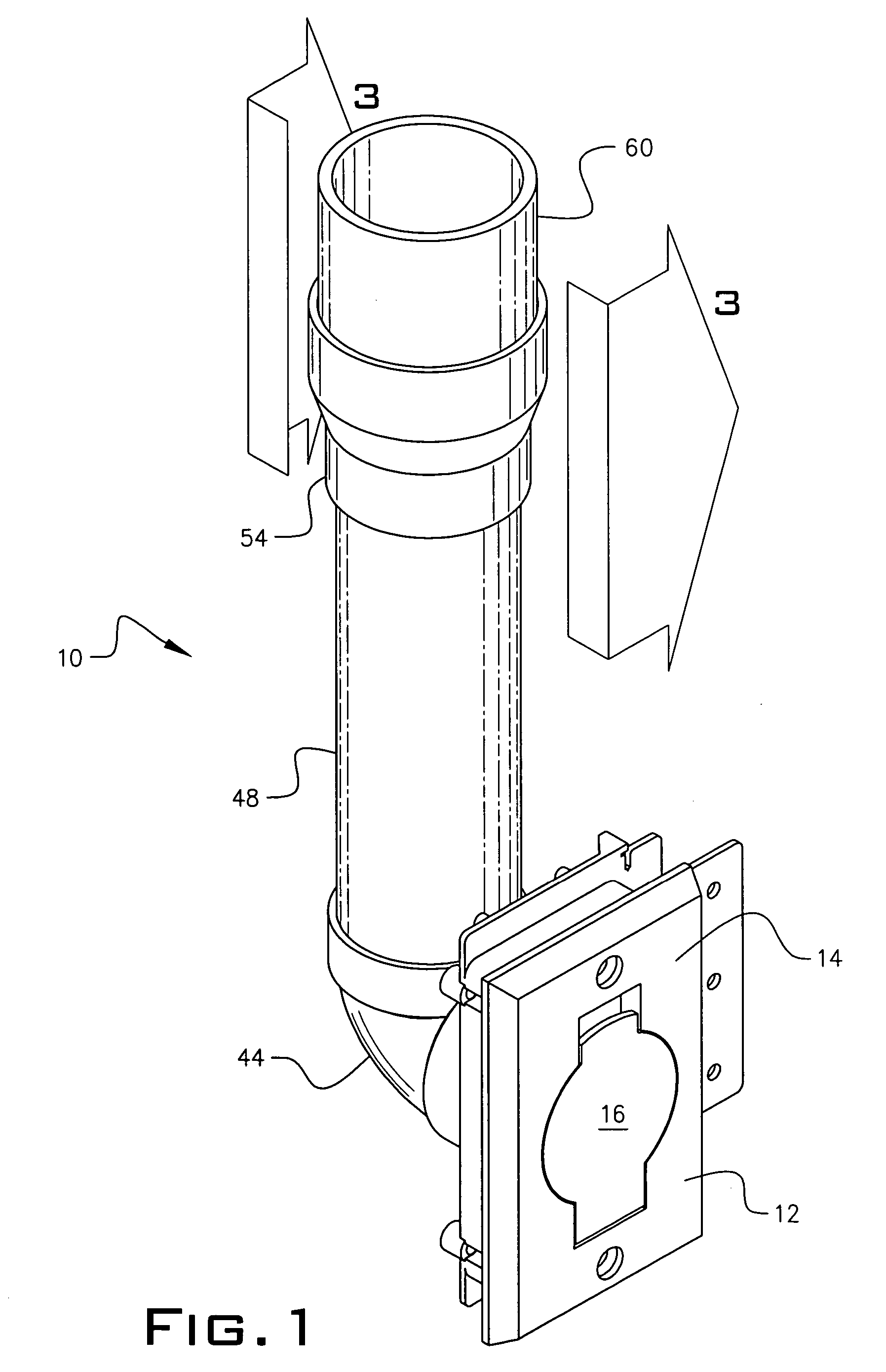
[0017]Referring to FIG. 1, a single section of a central vacuuming system 10 is shown. Central vacuuming system 10 includes a series of ports strategically located within the inner area of a residential or commercial building. FIG. 1 depicts one of those ports 12.

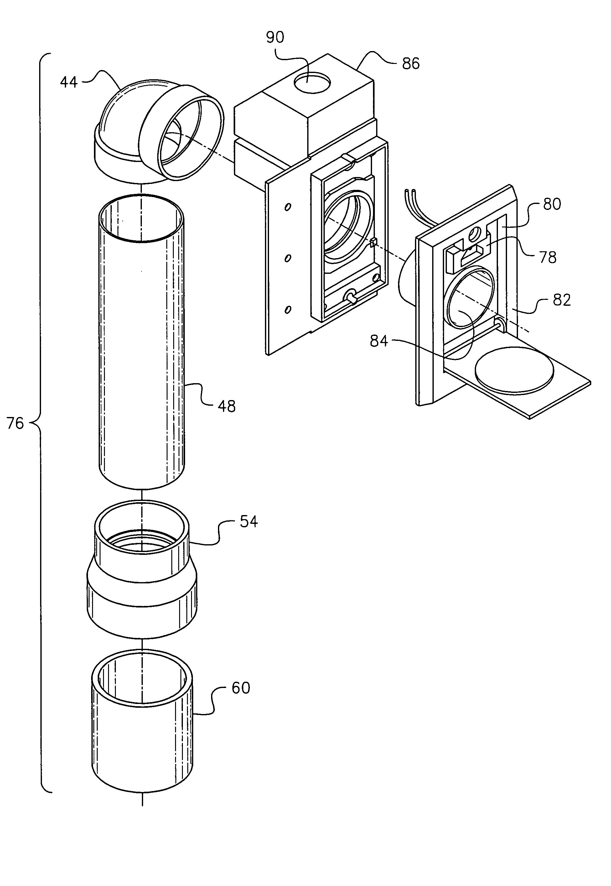
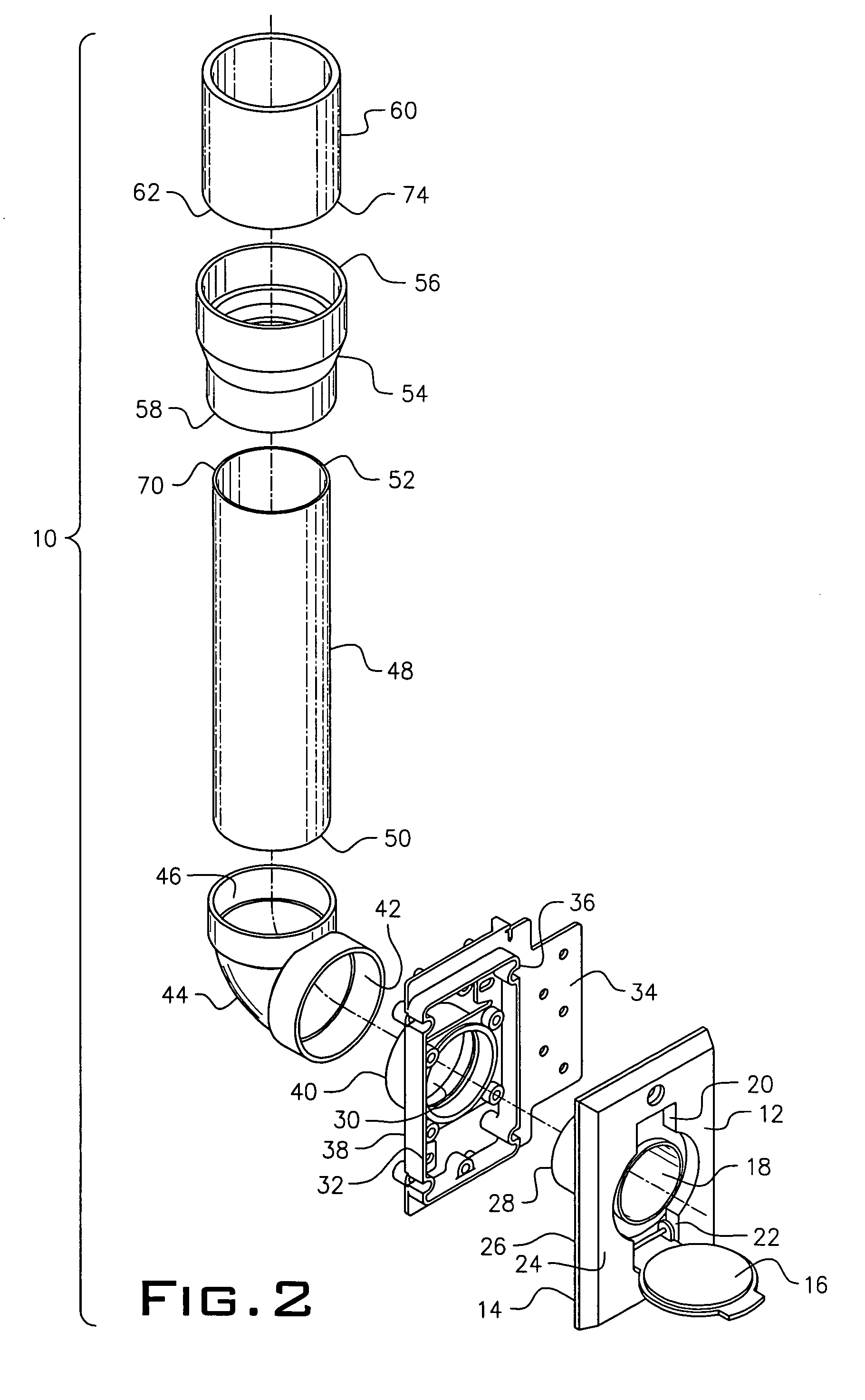
[0018]As shown in FIG. 2, port 12 includes a face plate 14 and a cover member 16 for closing off an opening 18 when not in use. In the preferred embodiment, cover member 16 is hinged at either a top or bottom end, 20 and 22 respectively. In the preferred embodiment, cover member 16 is hinged at bottom end 22. As further shown in FIG. 2, opening 18 is circular in shape. Port 12 includes a front and back side, 24 and 26 respectively. Face plate 14 is positioned on port front side 24. Port back side 26 has a rearwardly extending tubular member 28 which mates by axial alignment with an aperture 30 of an int...


PUM


Abstract

An in-wall central vacuuming system has a central receptacle and a vacuum pump for drawing dirt and dust into a network of piping and into the receptacle. The system includes a series of ports strategically located around an interior environment of a residential or commercial building. The series of ports permit a flexible tubular hose to be connected thereto. Each port includes an interior wall mounting plate positioned behind the port and has axially aligned circular openings for receiving the flexible tubular hose. An elbow positioned within the wall attaches to a rearwardly extending tubular portion of the mounting frame and attaches to an odd sized first pipe section. A coupler member attaches the odd sized first pipe section to a universally available second pipe section which is used to create a network of piping for the system.

Description

PRIOR APPLICATIONS[0001]This is a non-provisional application, whish bases priority on provisional application Ser. No. 60 / 478,274, filed Jun. 13, 2003, now abandoned.BACKGROUND OF THE INVENTION[0002]1. Field of the Invention[0003]This invention relates to a central vacuuming system located within the walls of residential or commercial buildings. In particular, it relates to a central vacuuming system that employs a coupler member within the wall of the building which permits the use of universally available piping to be used in conjunction with specialized piping employed with central vacuuming systems.[0004]2. Background of the Prior Art[0005]Central vacuuming systems for use in residential and commercial buildings are known. The systems typically employ a network of pipes positioned within the walls of the building such that they are not visible to the eye. A series of ports, acting as terminals or access points, are positioned around the building for permitting a user to attach ...

Claims


Application Information

Patent Timeline
IPC IPC(8): A47L5/38A47L9/24
CPCA47L9/242A47L5/38
Inventor AMBROSE, ROGER A.
Owner AMBROSE ROGER A
Why Eureka
Try Eureka