Collapsible structural members

a structural member and beam technology, applied in the direction of swimming pools, building roofs, portal frames, etc., can solve the problems of requiring substantial time to form a structure and collapse a structur

Active Publication Date: 2009-12-22
LUCO ED ENTERPRISES
View PDF29 Cites 33 Cited by
  • Summary
  • Abstract
  • Description
  • Claims
  • Application Information

AI Technical Summary

Problems solved by technology

Usually collapsible structural members require multiple parts and also require substantial time to form a structure and to collapse that structure.

Method used


Image

  • Collapsible structural members
  • Collapsible structural members
  • Collapsible structural members

Examples


Embodiment Construction

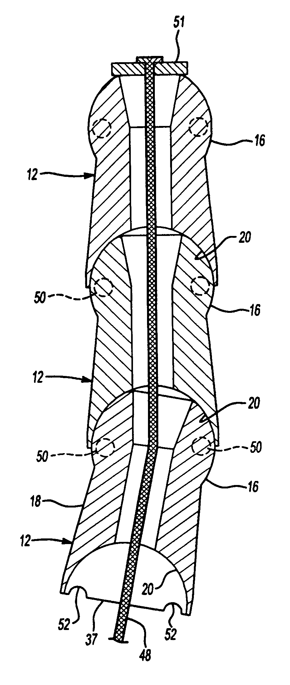
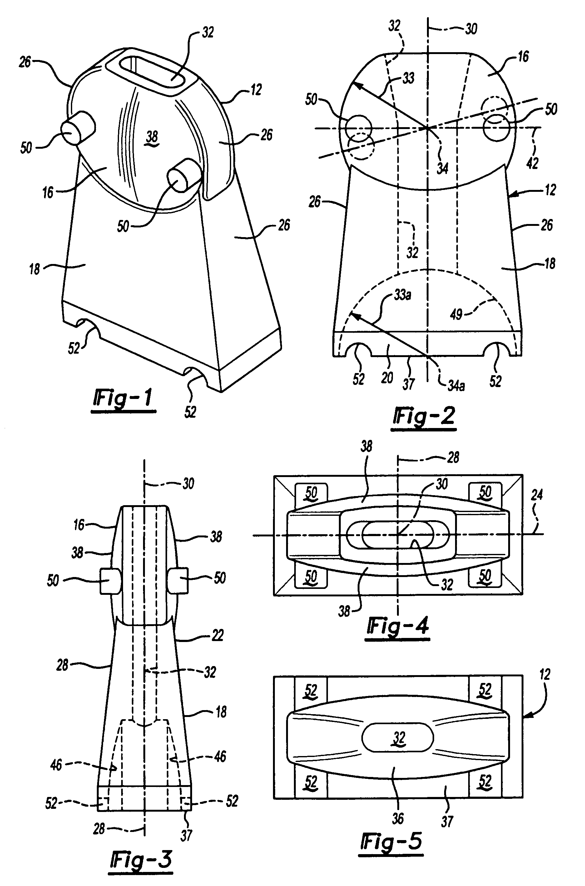
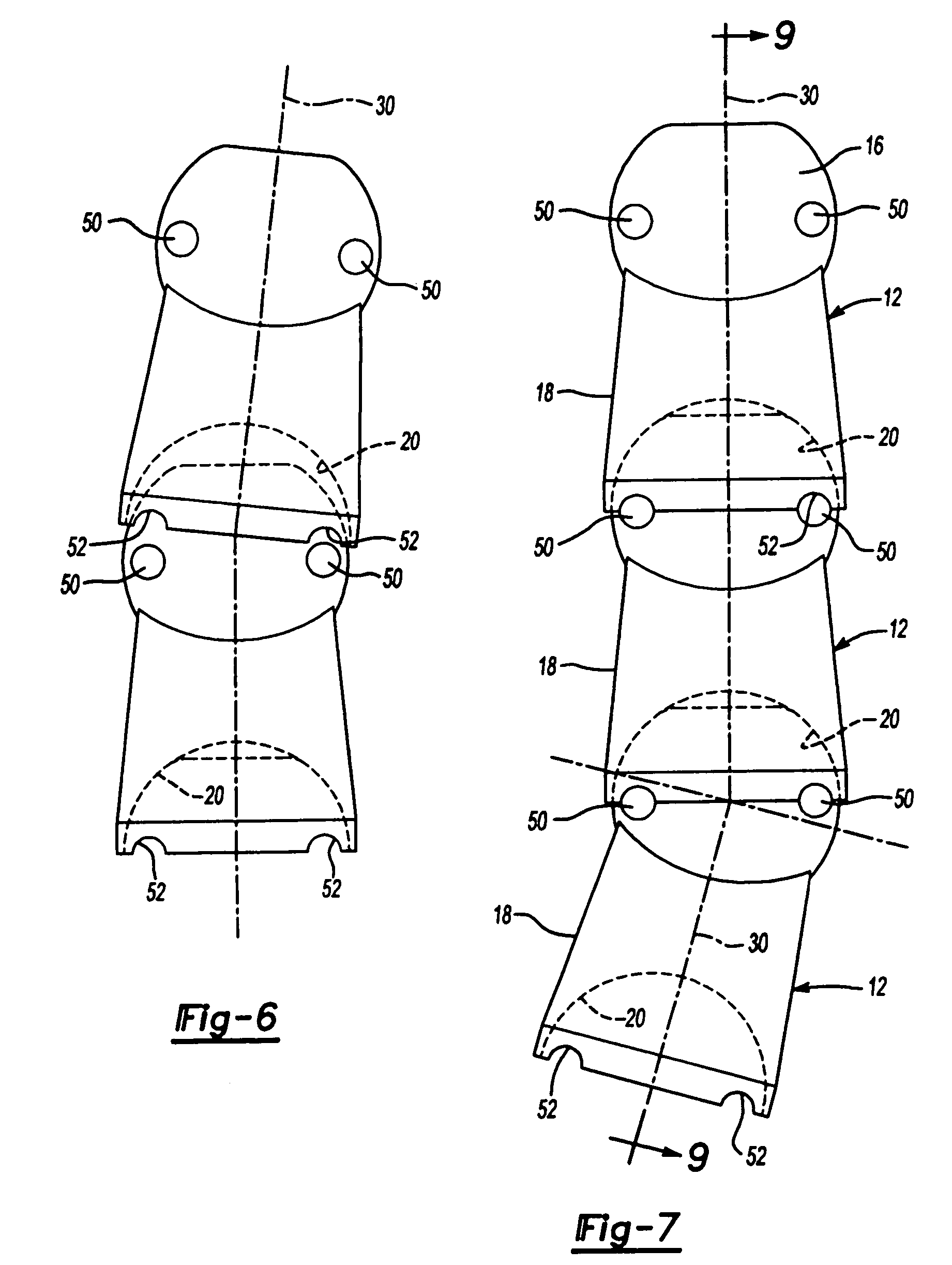
[0023]The present invention utilizes a concept of spherical frictional locking surfaces.

[0024]A common example of a frictional locking surface is the conical form found in the Morse taper invented by Steven A. Morse about 1864 and still in wide commercial use in drill presses and lathes. In such a locking arrangement the conical end of a shaft of a tool or drill bit has an included angle at the apex of about seven degrees (7°) or less. When the tool is inserted in a chuck having a complementary conical socket with the same included angle, friction alone maintains the tool in the socket. A small axial force applied to the tool to bring the tapered locking surfaces into engagement with each other is sufficient to frictionally lock the shank of the tool in torque transmitting relationship to the socket. A similar axial force in the opposite direction is applied to disconnect the tapered locking surfaces from each other.

[0025]The locking surfaces employed in the present invention uses o...


PUM


Abstract

A collapsible structural member has been provided in which substantially identical modules made up of metal or plastic are threaded on a tensioning member such as a cable and are movable relative to each other in the collapsed condition of the beam and are brought together into a condition where adjacent modules are locked together to form a rigid construction when the beam is in its erected operating condition. The beam is changed from its erected condition to its collapsed condition by relaxing the tensioning member or cable.

Description

FIELD OF THE INVENTION[0001]This invention relates to collapsible structural members or beams and more particularly to collapsible structural members which use substantially identical modules to form beam which are rigid in three dimensions.BACKGROUND OF THE INVENTION[0002]Various collapsible members have been used to form beams for collapsible structures such as temporary buildings and tents and also for work arms to position working tools in awkward locations. The collapsible structural members typically employ cables as tensioning members to bring separate segments or modules together to form a rigid structure. Such prior art structures usually rely on the cable itself to provide rigidity to the member or to separate pins or fasteners which must be installed to obtain rigidity and must be removed to permit collapse of the structure. Usually collapsible structural members require multiple parts and also require substantial time to form a structure and to collapse that structure.[0...

Claims


Application Information

Patent Timeline
Patent Type & Authority Patents(United States)
IPC IPC(8): E04H12/18
CPCE04H4/082E04C3/005
Inventor LUCAS, NICHOLAS G.
Owner LUCO ED ENTERPRISES
Why Eureka
Try Eureka