Panel attachment clip

a technology of attachment clips and ceiling panels, which is applied in the direction of ceilings, walls, roofing, etc., can solve the problems of difficult positioning of anchor points for suspension wires, difficult hanging of suspension wires, and high time consumption, and achieve quick and accurate suspension of free-form ceiling panels, easy installation and locking

Active Publication Date: 2009-12-29
USG INTERIORS INC
View PDF16 Cites 21 Cited by
  • Summary
  • Abstract
  • Description
  • Claims
  • Application Information

AI Technical Summary

Benefits of technology

[0003]The invention provides a system for quickly and accurately suspending free-form ceiling panels. The system relies on a novel clip for connecting the panels to a set of overlying channels. The channels are situated in a plane just above the plane in which the ceiling panels are to be hung. With the channels suitably in place, the clips are assembled on the channels. The illustrated clips are readily installed and locked onto the channels without the need for separate fasteners or tools. Once the clips are assembled on the channels, the ceiling panels can be hung on the clips and thereby be suspended by the channels. The clips preferably have bendable tabs that, when deployed, lock the panels against accidental or unauthorized vertical movement and consequent separation from the clips.
[0004]In one embodiment of the clip, a panel engaging hook is pivotally connected to upper portions of the clip. The pivot connection allows the hook to be twisted about a vertical axis to an angle that matches the angle between the edge of the panel to be supported and the respective channel.

Problems solved by technology

Some overhead structures or super-structures make it difficult to hang suspension wires, particularly when such wires are required on specific overhead centers.
When the suspended ceiling is a so-called free-form type and does not have a rectangular or an otherwise regular pattern, the layout of the anchor points for the suspension wires is difficult and can be extremely time consuming.
This condition can tax the skill and patience of the installer in an effort to find the best compromise to avoid shifting and / or distortion of the ceiling panels because of the side forces developed by angled suspension wires.

Method used


Image

  • Panel attachment clip
  • Panel attachment clip
  • Panel attachment clip

Examples


Embodiment Construction

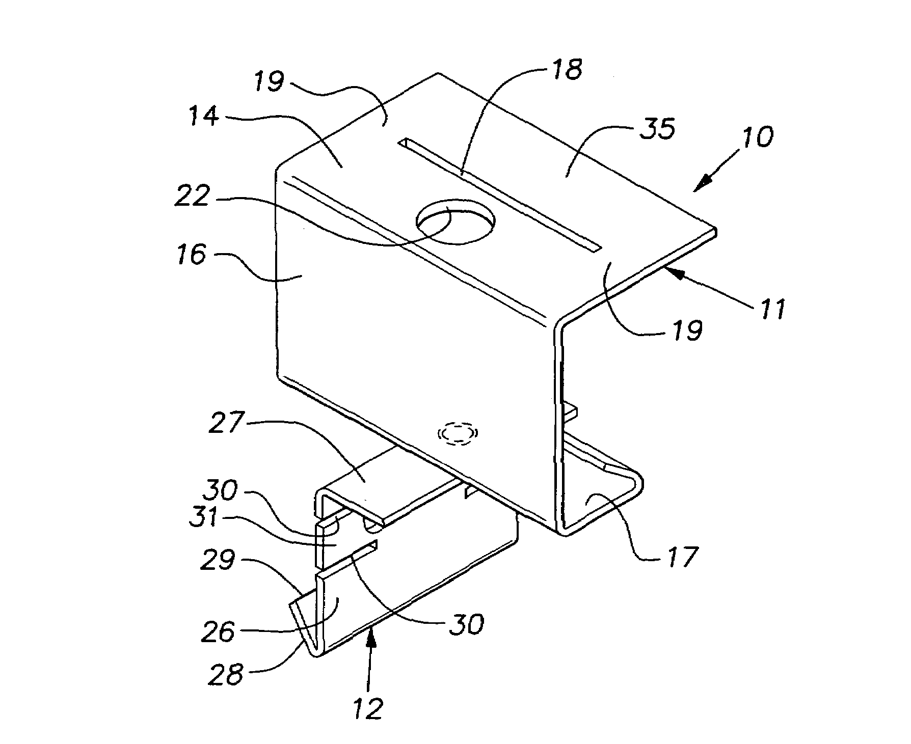
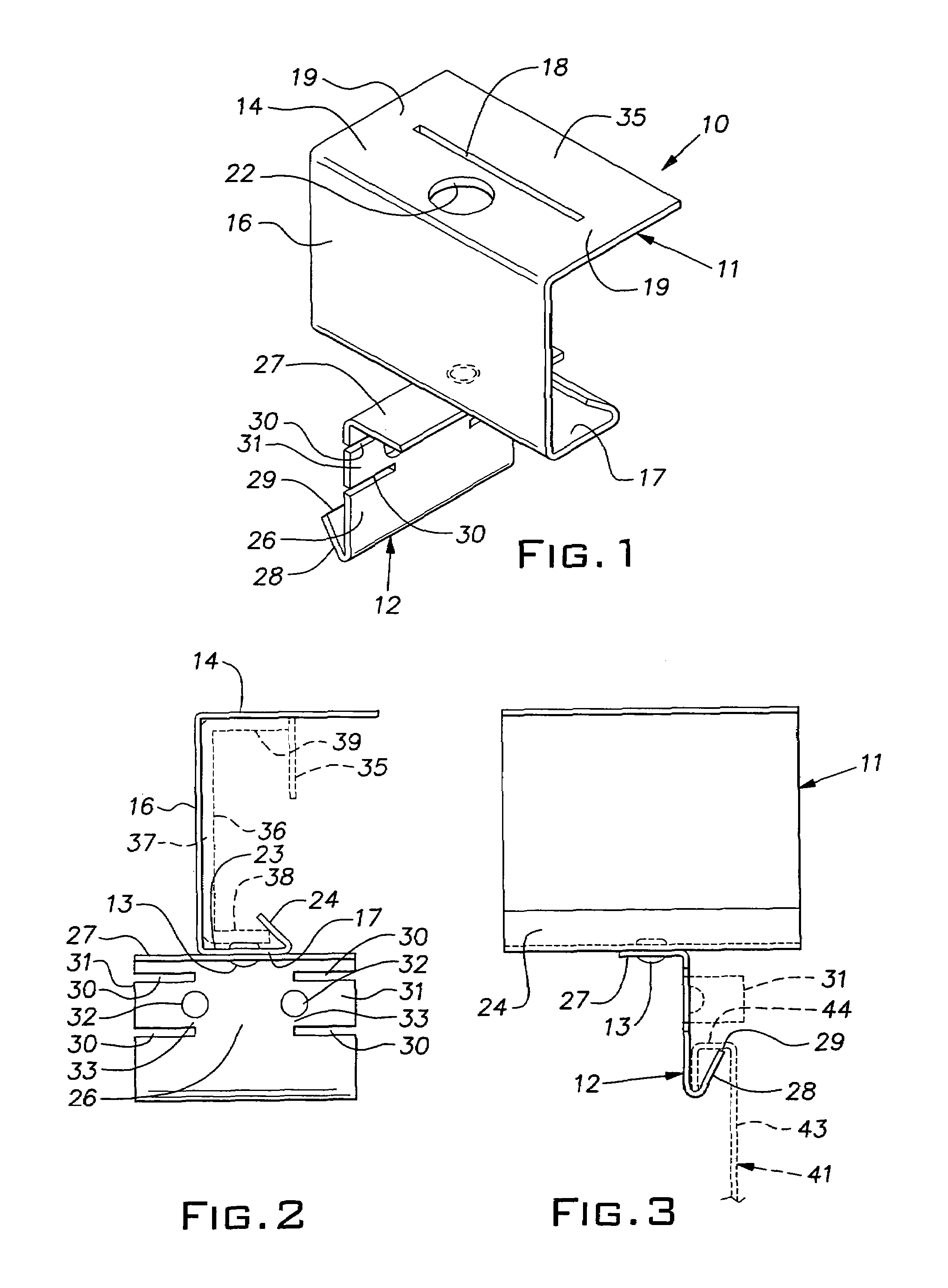
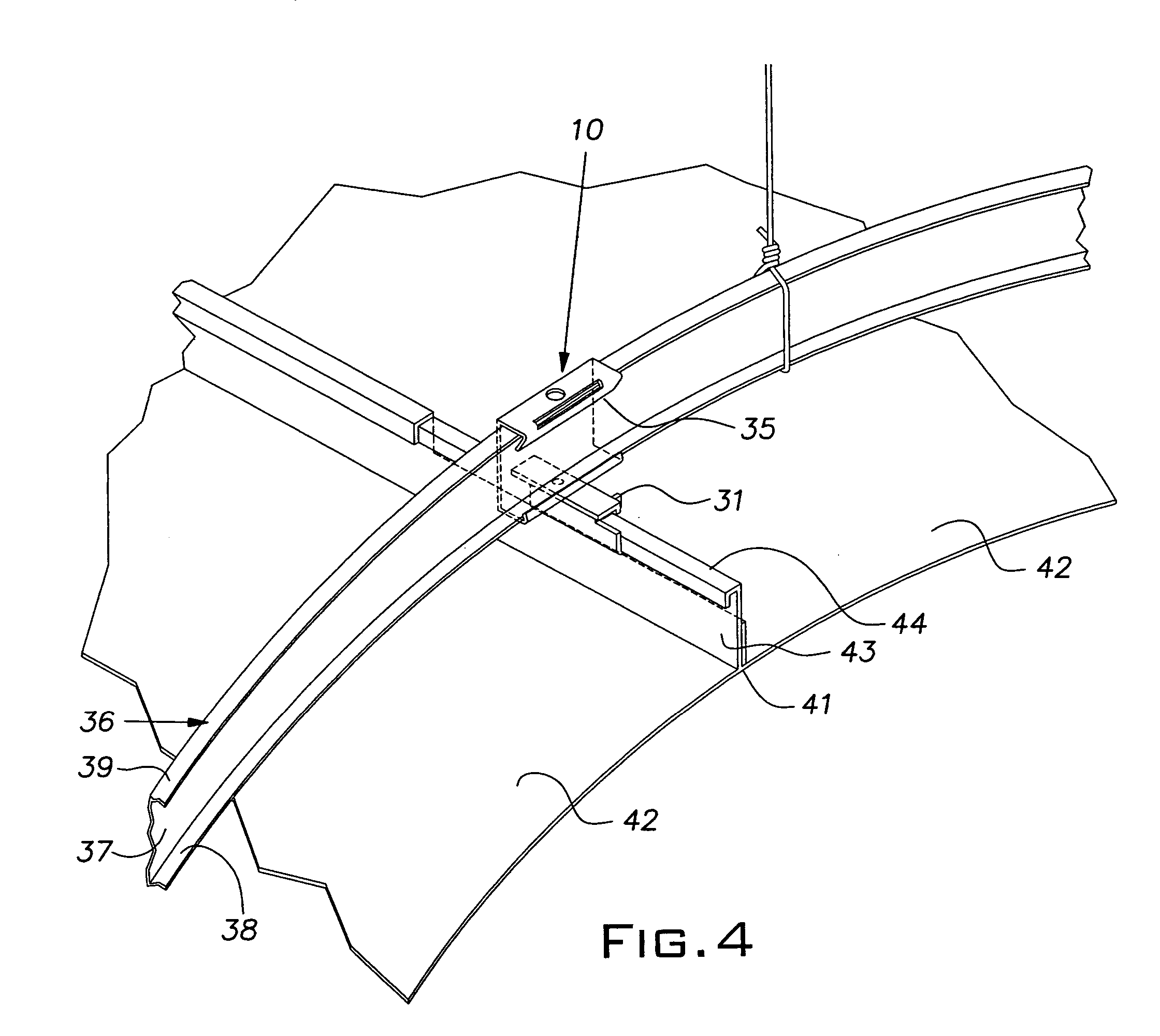
[0012]Referring now to the drawings and, in particular, to FIGS. 1-3, there is shown a first embodiment of the panel attachment clip 10 of the invention. The clip or bracket 10 is a body formed of two pieces of steel sheet or other suitable metal. The clip includes an upper part 11 and a lower part 12 permanently joined together by a rivet 13. The upper part 11, initially, has a flat horizontal section 14, a vertical web 16 and a bottom section 17. The top section 14 has an elongated slot 18 leaving small land areas 19 at each end so as to establish a bend line through the slot and the land areas 19 parallel to the web 16. A hole 22 in the top section 14 provides access for a tool to install the rivet 13. The bottom section 17 has a horizontal zone 23 with an integral reversely bent or re-entrant lip 24 that, as described later, catches on the flange of a supporting channel shown in phantom at 36 in FIG. 2.

[0013]The lower part 12 of the clip body has a vertical web 26 and an integra...


PUM


Abstract

A clip for suspending ceiling panels from a horizontal channel having a C-shape formed by a vertical web and integral opposed horizontal upper and lower flanges, the clip comprising a sheet metal body, the body including a vertical web extending between upper and lower portions, the upper portion being configured to overlie the horizontal upper flange of the channel when installed thereon, the lower portion being configured to lie below the horizontal lower flange of the channel, the lower portion including a generally upstanding hook section adapted to be received in a downwardly open channel on the ceiling panel beneath the C-shaped channel to enable the clip to support the panel by transferring the weight of the panel to the C-shaped channel, the hook section being fixed against horizontal movement relative to the body vertical web.

Description

BACKGROUND OF THE INVENTION[0001]The invention relates to suspended ceilings and, in particular, to improvements in gridless type suspended ceilings.PRIOR ART[0002]U.S. Pat. No. 6,763,641 discloses a suspended ceiling construction that uses non-rectangular planks or metal pans butted together at their edges and supported directly by overhead suspension wires. Some overhead structures or super-structures make it difficult to hang suspension wires, particularly when such wires are required on specific overhead centers. When the suspended ceiling is a so-called free-form type and does not have a rectangular or an otherwise regular pattern, the layout of the anchor points for the suspension wires is difficult and can be extremely time consuming. Typically, a convenient anchor point will not lie directly above a location where a ceiling panel is designed to receive a wire. This condition can tax the skill and patience of the installer in an effort to find the best compromise to avoid shi...

Claims


Application Information

Patent Timeline
Patent Type & Authority Patents(United States)
IPC IPC(8): E04B2/00
CPCE04B9/225E04B9/28E04B9/06
Inventor AHREN, GREGORY M.BANKSTON, JOHN D.FLETTERICK, JAMES A.
Owner USG INTERIORS INC
Why Eureka
Try Eureka