Adjustable utility light and methods of use thereof

a technology of utility lights and adaptable light bodies, which is applied in the direction of lighting and heating apparatus, semiconductor devices for light sources, and support devices for lights. it can solve the problems of awkward and inefficient in tight confinement, light handling that is typically severe, and limited illumination direction of utility lights

Inactive Publication Date: 2010-01-19
ELUMX
View PDF10 Cites 18 Cited by
  • Summary
  • Abstract
  • Description
  • Claims
  • Application Information

AI Technical Summary

Benefits of technology

[0027]Accordingly, a feature and advantage of the present invention is its ability to provide augmented light through use of a pivoting reflector.
[0028]Another feature and advantage of the present invention is its ability to pivot its lamp portion from 0 to slightly greater than 90 degrees (or up to 180 degrees in an alternate embodiment).
[0029]Still another feature and advantage of the present invention is its ability to be supported by retractable hooks.
[0030]Yet still another feature and advantage of the present invention is its ability to be secured to a variety of profiles, such as, rods, doors, flat surfaces, automobile hoods and latches for same, edge of a block and the like, or suspended from a line or cable.
[0031]Yet a further feature and advantage of the present invention is that it provides a work tray for secure support and retention of small components.
[0032]Yet still a further feature and advantage of the present invention is that it provides light 360 degrees around its lamp portion.

Problems solved by technology

Such lights typically undergo severe handling and are often utilized in close quarters.
Often, the direction of illumination of the utility light is limited to the positioning of the utility light itself, which can be quite awkward and inefficient in a tightly confined workspace.
Those who have used utility lights will quickly recognize that because of the frequently changing location of the utility light, finding a location for hanging and correctly orienting the light is often difficult.
However, both incandescent light sources and fluorescent light sources comprise glass bulbs or tubes that are subject to breakage and which thus must be protected, typically by a rigid metal screen shell (that casts shadows) or where unimpeded radiation is required, by a clear plastic lens that adds complexity and weight to the lighting device, and also reduces light by about 10%.
However, once installed (hanging by its hooks or lying on a flat surface), the lamp lacks a facility for further adjustment.
Further, hooks that protrude can be bent, broken or can snag on other objects during use and / or transport.
While this provides some flexibility, it does not adequately provide the ability to illuminate different areas unless the device is removed from its support.
Further, because the pivoting movement is part of the bulb removal operation, the bulb is exposed when pivoted, thereby rendering the bulb susceptible to damage and the user to potential injury from broken glass and / or burns.
Yet another prior utility flashlight provides a hook at the top thereof, but, while portable, requires a heavy battery base for operation.
This device further provides a snap-on reflector that facilitates directing of light; however, this reflector is a separate component that can become misplaced and thus unavailable.

Method used


Image

  • Adjustable utility light and methods of use thereof
  • Adjustable utility light and methods of use thereof
  • Adjustable utility light and methods of use thereof

Examples


Embodiment Construction

[0047]In describing the preferred and selected alternate embodiments of the present invention, as illustrated in FIGS. 1-7B, specific terminology is employed for the sake of clarity. The invention, however, is not intended to be limited to the specific terminology so selected, and it is to be understood that each specific element includes all technical equivalents that operate in a similar manner to accomplish similar functions.

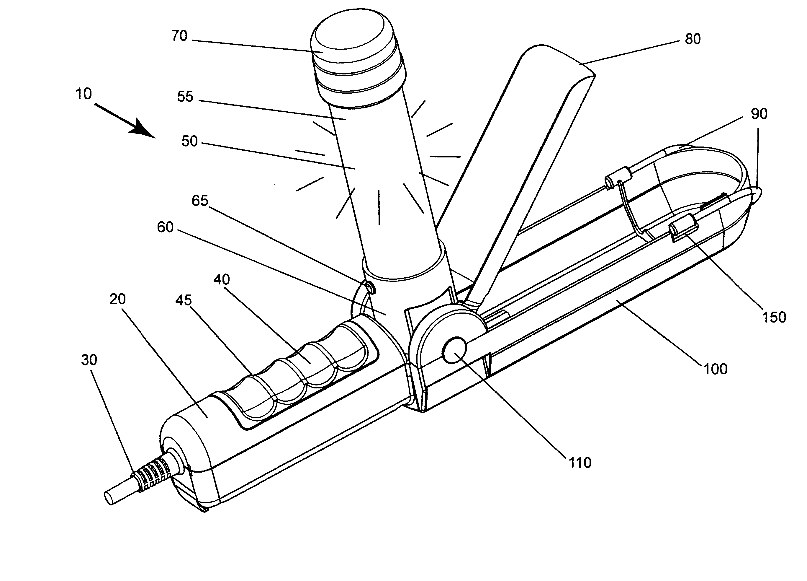
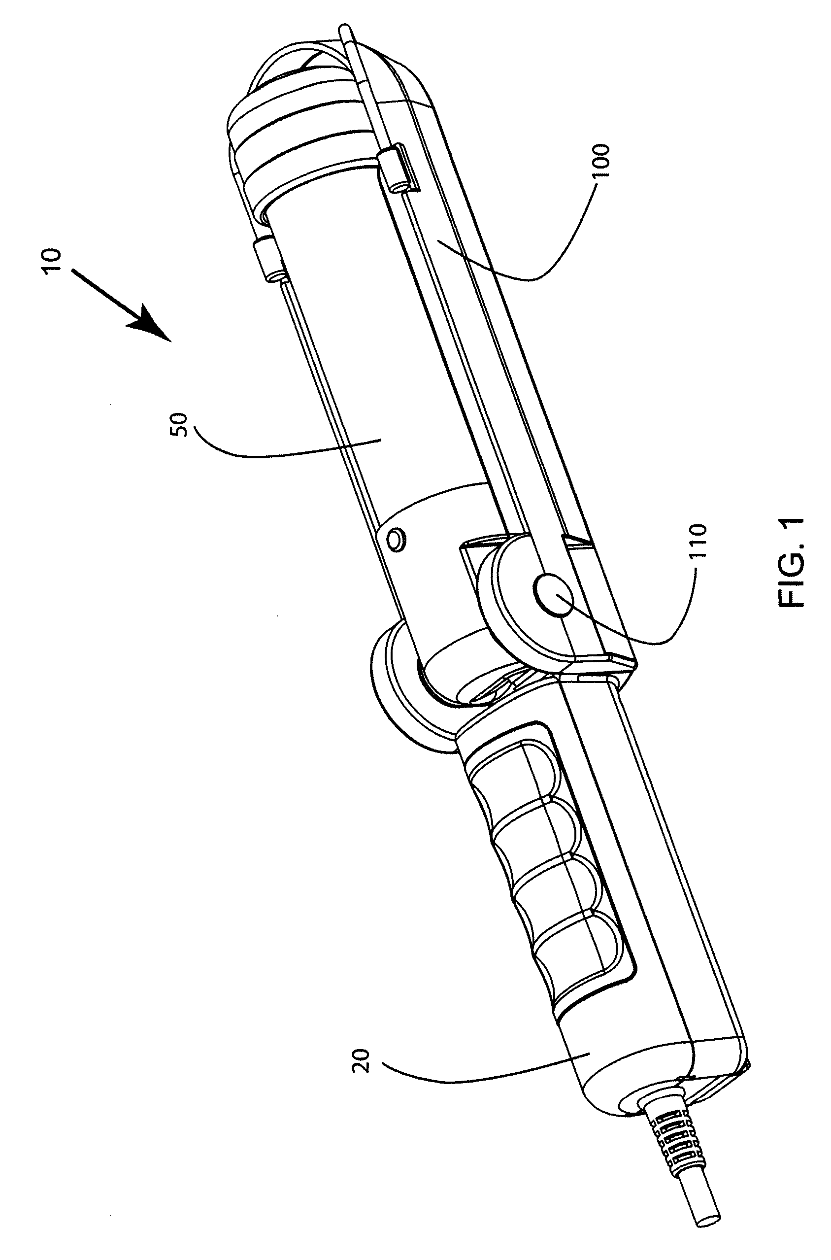
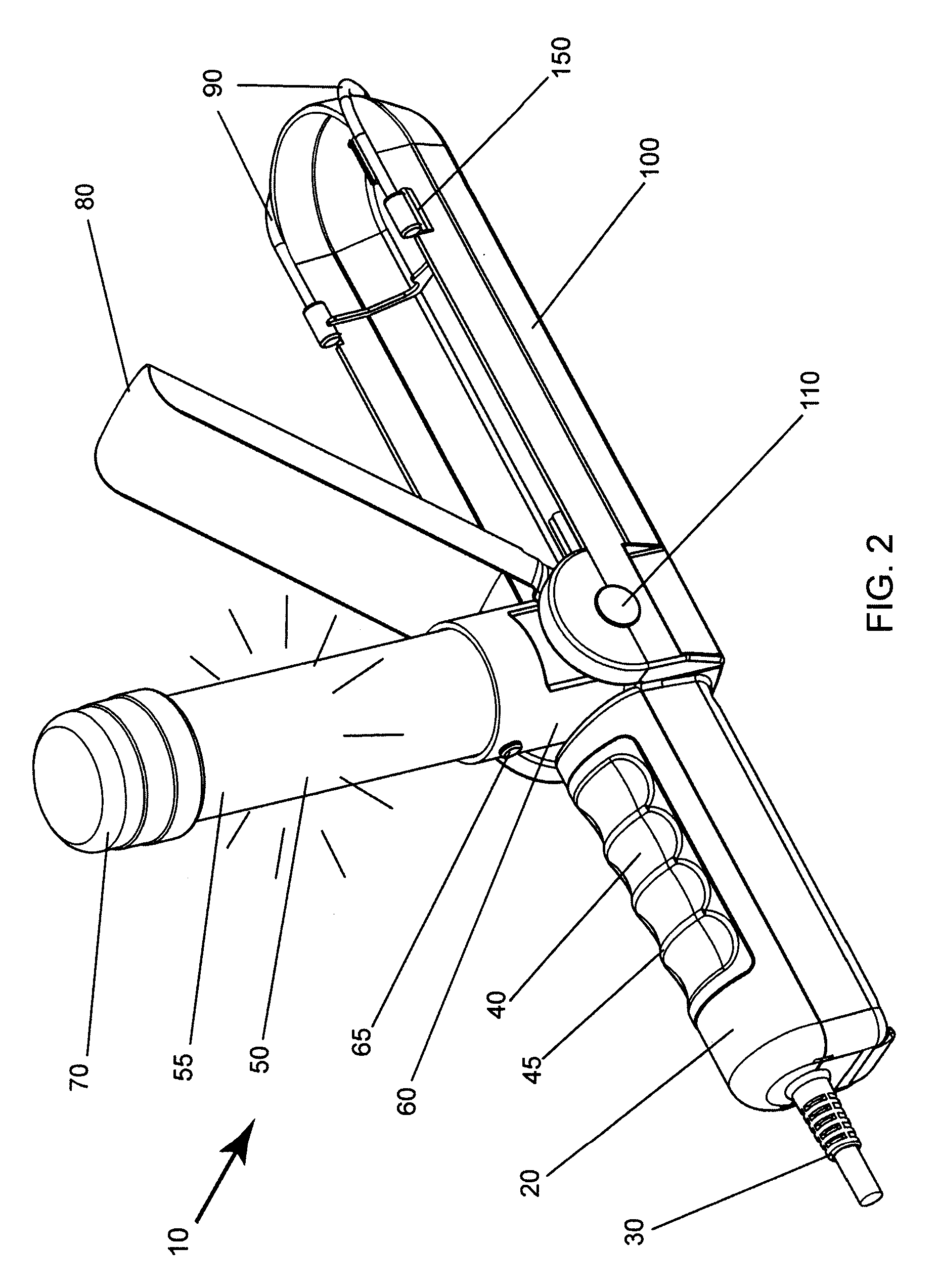
[0048]Referring now to FIGS. 1-5A and 6, the present invention in a preferred embodiment is adjustable utility light 10, wherein adjustable utility light 10 preferably comprises handle section 20, power cord 30, lamp section 50, reflector 80, hooks 90, tray 100 and switch 120 (best shown in FIG. 3). Lamp section 50 and reflector 80 are preferably pivotally attached to tray 100, wherein pivot 110 provides a common axis for lamp section 50 and reflector 80 at junction of tray 100 with handle section 20.

[0049]Grip 40 is preferably disposed on handle section 20, ...


PUM


Abstract

An adjustable utility light having a body section, two independently movable hooks, a pivoting lamp section having fluorescent tubes and / or light emitting diodes, a component retention tray, at least one keyhole mounting slot, and a movable reflector, wherein the pivoting lamp section and the movable reflector pivot about the same pivot axis.

Description

CROSS-REFERENCE TO RELATED APPLICATIONS[0001]NoneFEDERALLY SPONSORED RESEARCH OR DEVELOPMENT[0002]NonePARTIES TO A JOINT RESEARCH AGREEMENT[0003]NoneREFERENCE TO A SEQUENCE LISTING[0004]NoneBACKGROUND OF THE INVENTION[0005]1. Technical Field of the Invention[0006]The present invention relates generally to utility lights, and more specifically to an adjustable task, ‘trouble’, drop or work light with multiple suspension or mounting options, wherein a lamp section pivots open up to slightly greater than 90 degrees (or up to 180 degrees in an alternate embodiment) exposing the lamp section from one or both sides when in use, thereby providing the ability to aim the light in a selected direction or at a selected area. A pivoting reflector may selectively be utilized to augment and direct light where desired.[0007]2. Description of Related Art[0008]Task or utility lights are typically utilized to extend light into a non-illuminated or poorly illuminated location, often remote from a powe...

Claims


Application Information

Patent Timeline
Patent Type & Authority Patents(United States)
IPC IPC(8): F21V21/00
CPCF21L14/02F21V14/02F21V14/04F21V21/26F21Y2101/02F21Y2103/00F21Y2115/10
Inventor KO, WAI-SHING PETERGIBSON, JON ERIC
Owner ELUMX
Why Eureka
Try Eureka