
Application of data-binding mechanism to perform command binding

a command binding and data binding technology, applied in the field of computer processing, can solve the problems of frequent difficulty in working together productively between designers and developers, process clumsiness, and loss of design parts in the process

Active Publication Date: 2010-01-26
MICROSOFT TECH LICENSING LLC
View PDF22 Cites 13 Cited by
  • Summary
  • Abstract
  • Description
  • Claims
  • Application Information

AI Technical Summary

Problems solved by technology

Graphic design and software development are two very different disciplines and it is frequently difficult for designers and developers to work together productively.
The original graphic design elements are typically not re-used in the final implementation and sometimes, parts of the design are lost in the process because the developer either cannot easily recreate the design in code or does not fully understand the design.
In short, the process is clumsy.
Another problem encountered when architecting such an application is how to expose functionality (commands) and how to map or bind that functionality to elements in the UI.
However, this mechanism is not very flexible.
Unfortunately, this mechanism is rather complex and difficult to master.

Method used


Image

  • Application of data-binding mechanism to perform command binding
  • Application of data-binding mechanism to perform command binding
  • Application of data-binding mechanism to perform command binding

Examples


Embodiment Construction

Overview

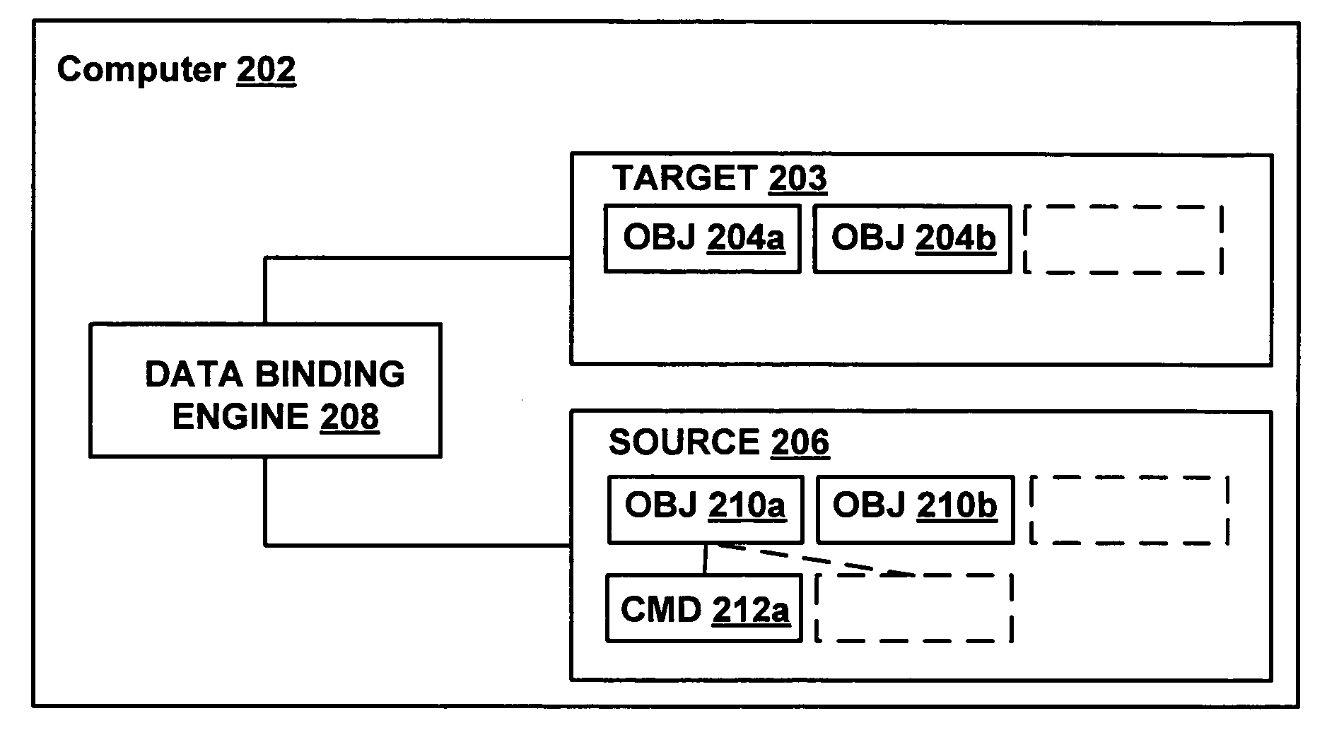
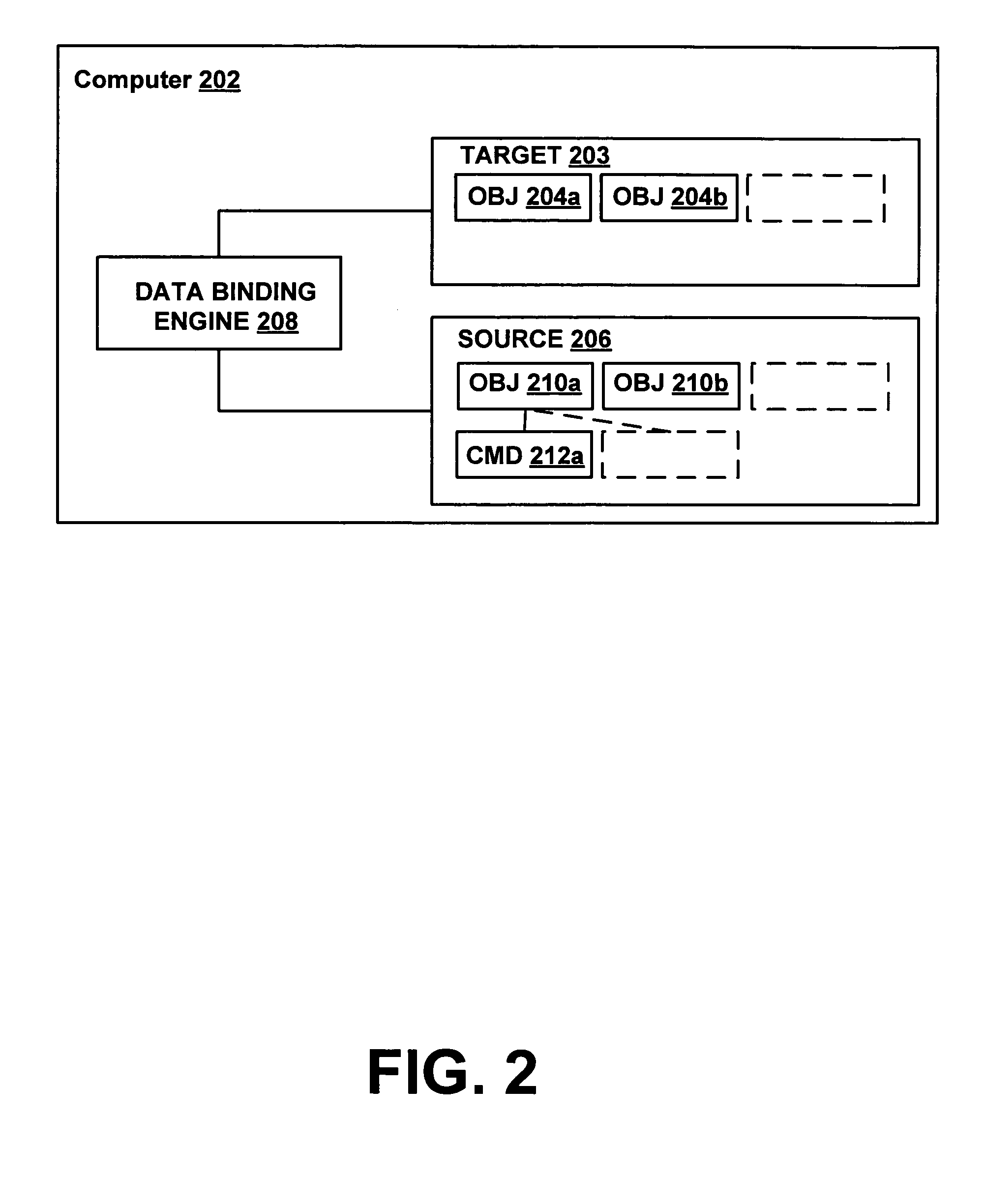
[0017]Suppose a text processing application handles a number of document objects that expose functionality for cutting selected text. The application may provide a menu item labeled “Cut” on the “Edit” menu. The application needs to define how the “Cut” command binds to the menu item and to the active document. Traditional methods of command binding are complex and add to the difficulties inherent in designer / developer interaction. In accordance with some embodiments of the invention, command binding is accomplished by declaratively associating data binding command paths to elements or components of a user interface, sending change notifications when a command property changes and updating the target automatically by a object-binding mechanism, thereby decreasing the complexity level and the need for technical expertise in command binding and routing.

Exemplary Computing Environment

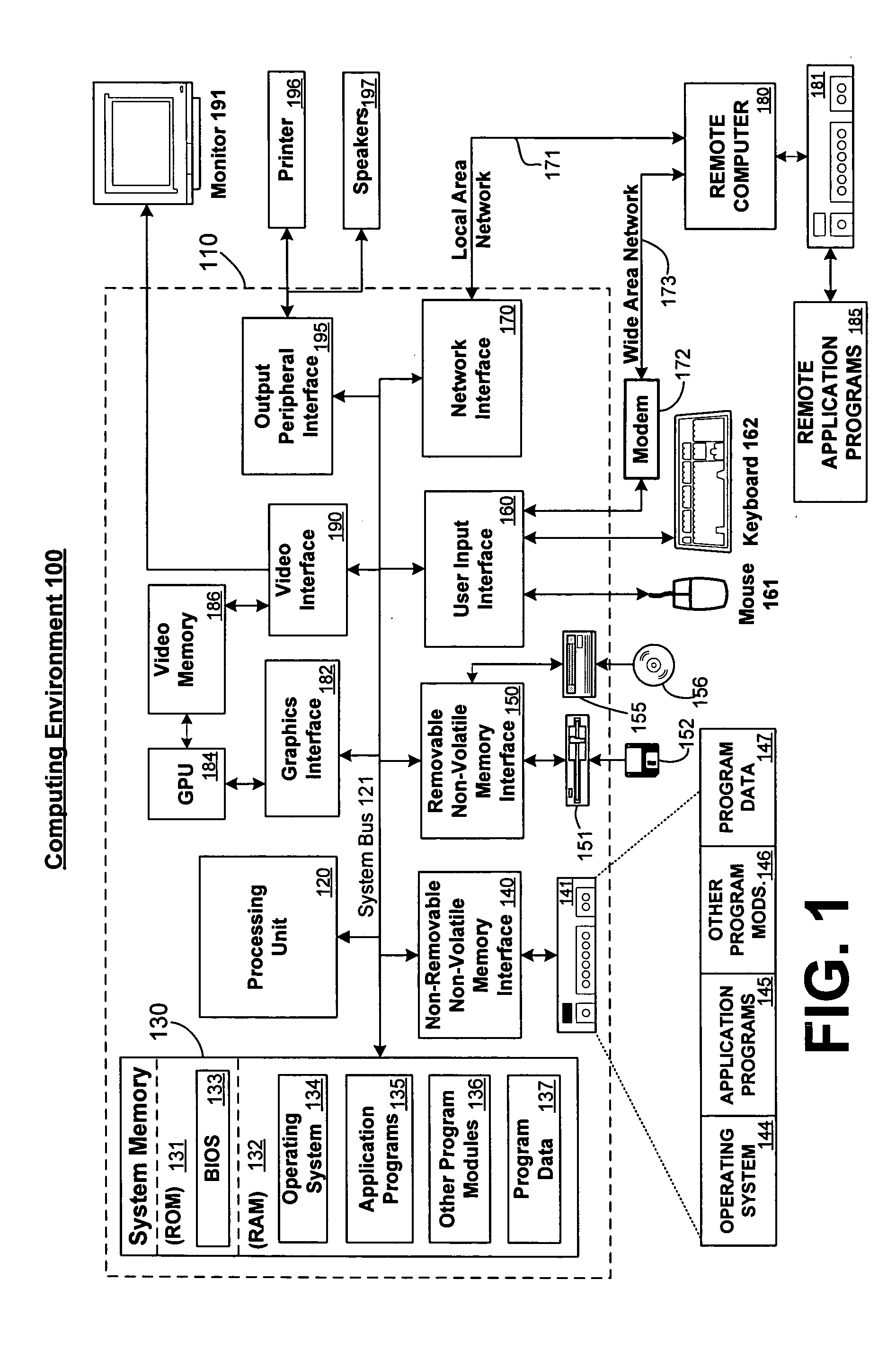
[0018]FIG. 1 and the following discussion are intended to provide a brief general description o...


PUM


Abstract

A data-binding engine is used to perform command binding. A data binding engine binds user interface controls such as buttons, menus, list boxes, etc. to commands exposed on an application model. A data source and data binding path may be specified in a markup language that defines how the commands are bound to UI elements.

Description

CROSS-REFERENCE TO RELATED APPLICATIONS[0001]The application is related to patent application Ser. No. 10 / 823,461 entitled “PRIORITY BINDING”, filed herewith.FIELD OF THE INVENTION[0002]The invention relates to computer processing and in particular to using a data-binding mechanism for command binding.BACKGROUND OF THE INVENTION[0003]The code for application programs is frequently separated into a layer for user interaction (a set of “views” or user interfaces (UIs)) and a layer for implementing the internal application logic and data management (often realized through a set of “models”). The user interface typically includes menu items and other UI elements that invoke functionality implemented on the models.[0004]Typically, a graphic designer designs the look of the user interface while a developer writes the code that implements the user interface and / or the underlying model. Graphic design and software development are two very different disciplines and it is frequently difficult...

Claims


Application Information

Patent Timeline
Patent Type & Authority Patents(United States)
IPC IPC(8): G06F3/00
CPCG06F8/38G06F8/315G06F8/65G06F9/445
Inventor PETERS, TED ANDREWCOOPER, KENNETH BRUCERODER, LUTZBENT, SAMUEL W.GUPTA, NAMITAJENNI, DAVID J.
Owner MICROSOFT TECH LICENSING LLC
Learn More