Magnetic tilt and raise/lower mechanisms for a venetian blind

a technology of venetian blinds and levers, applied in the field of venetian blinds, can solve the problems of large force required to overcome the coefficient of static friction between external magnets, abrasive external magnets of many such designs, rendering the window aesthetically unappealing, etc., and achieve the effect of facilitating the raising, lowering and tilt adjustmen

Active Publication Date: 2010-03-02
MASONITE CORP
View PDF49 Cites 43 Cited by
  • Summary
  • Abstract
  • Description
  • Claims
  • Application Information

AI Technical Summary

Problems solved by technology

Various problems exist with such conventional designs.
The external magnets of many such designs are abrasive against the glass pane.
As such, movement of the external magnets over the glass panes often results in scratching and marking of the glass panes after extended use, rendering the window aesthetically unappealing.
In addition, a significant amount of force is required to overcome the coefficient of static friction between the external magnets and the glass panes when the internal mechanisms are actuated.
This may result in an operator applying excessive forces to the external magnets, which may break the magnetic union between the external magnets and the internal tilt and / or lift mechanisms.

Method used


Image

  • Magnetic tilt and raise/lower mechanisms for a venetian blind
  • Magnetic tilt and raise/lower mechanisms for a venetian blind
  • Magnetic tilt and raise/lower mechanisms for a venetian blind

Examples


Embodiment Construction

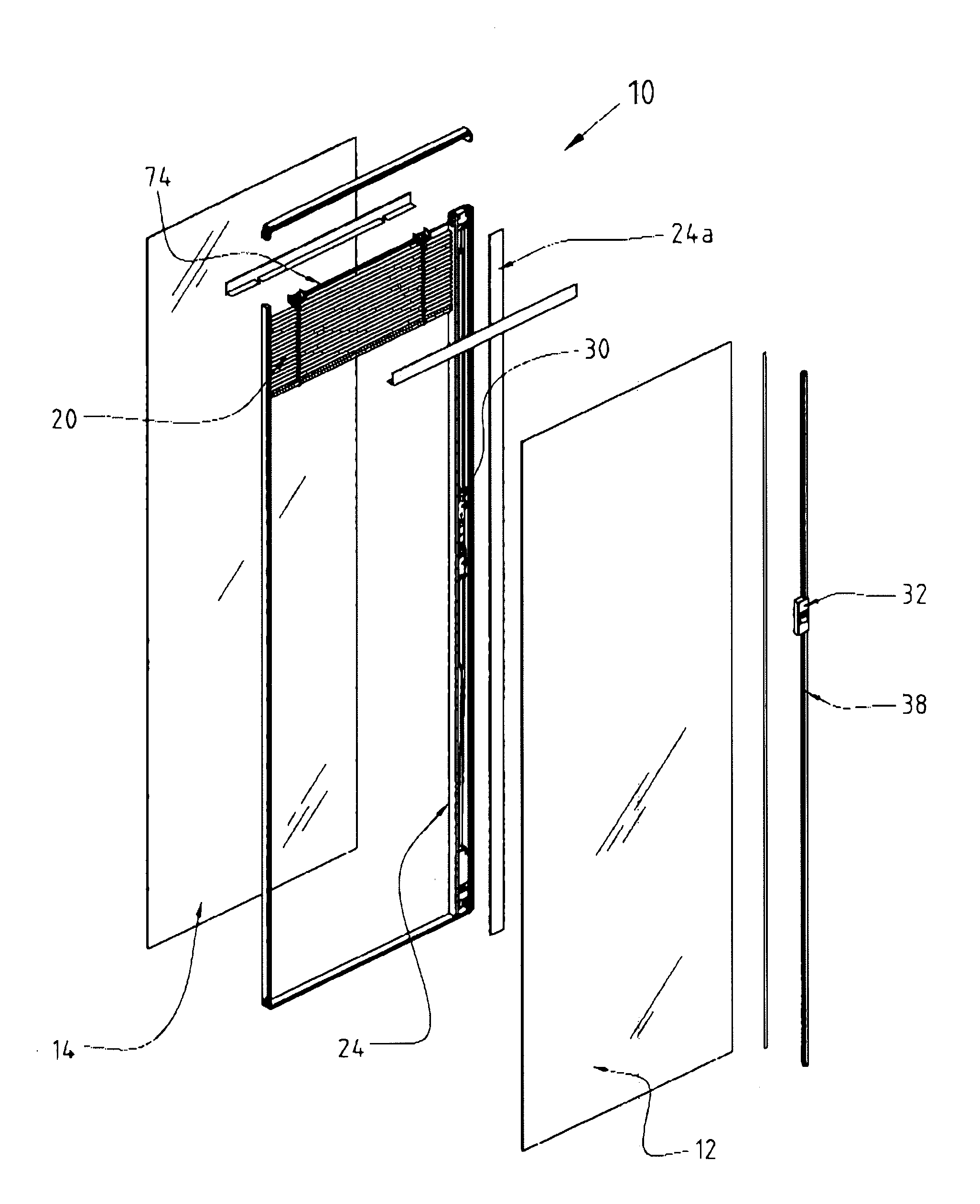
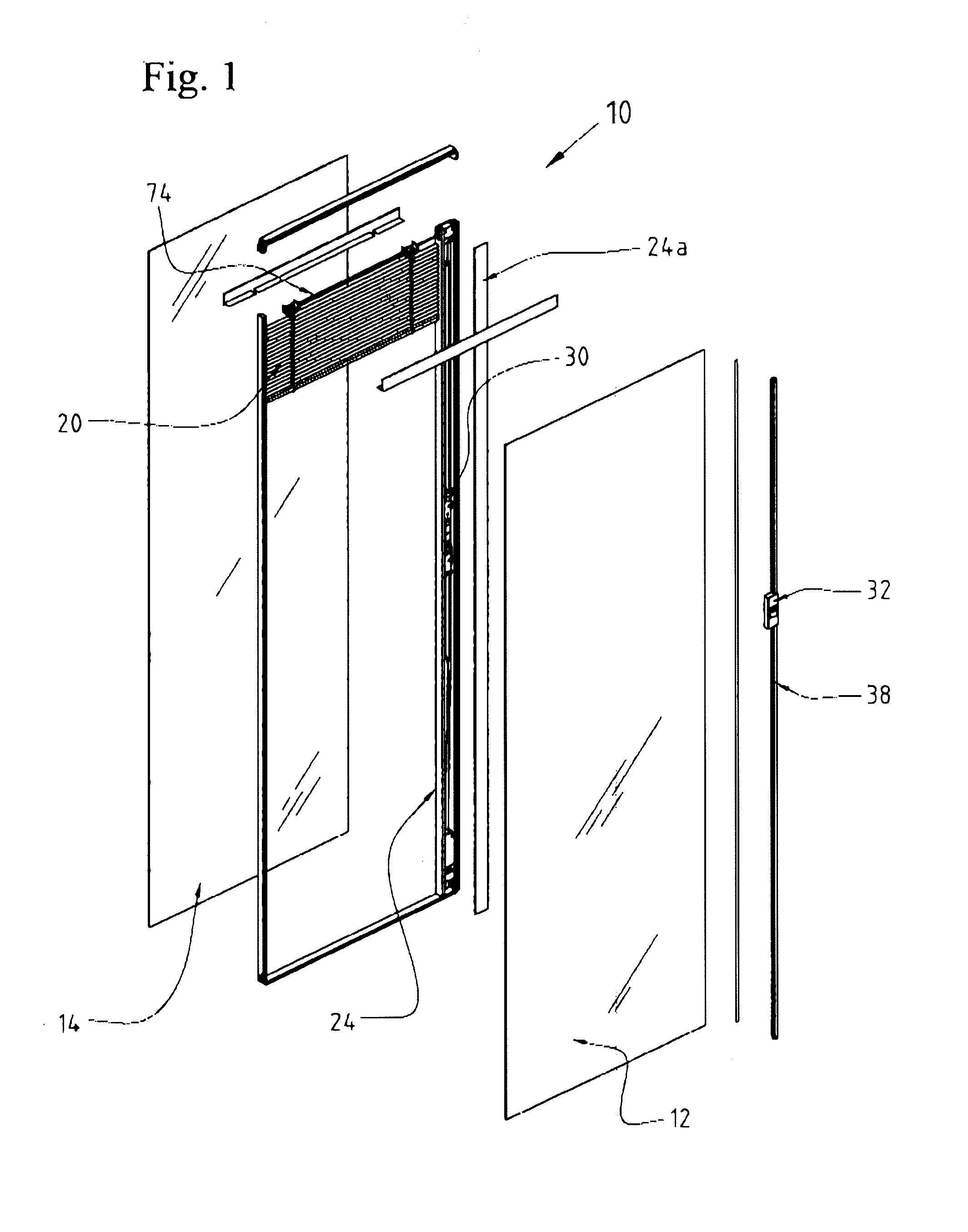
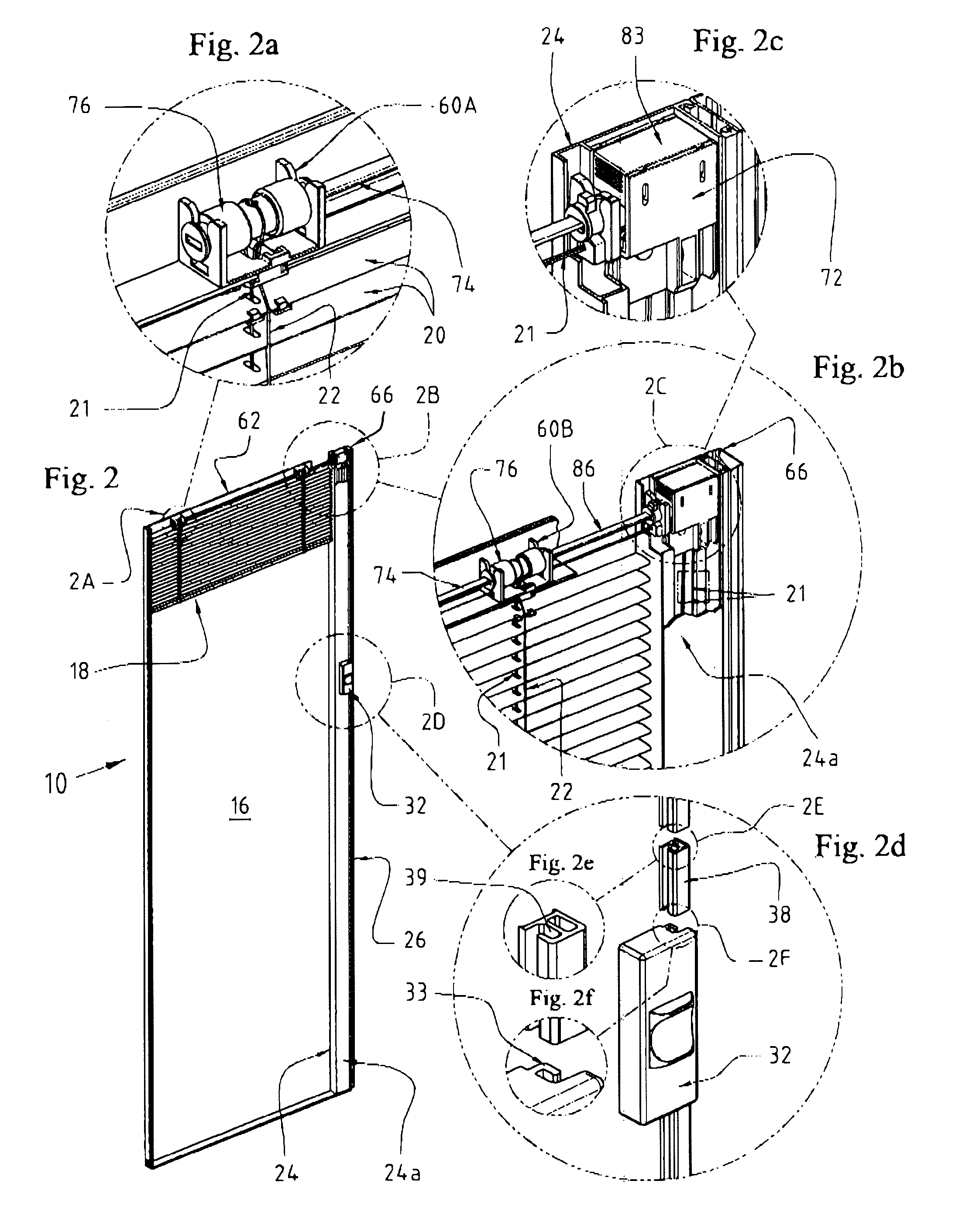
[0073]A window blind assembly 10 according to the present invention is best shown in FIGS. 1 and 2. Assembly 10 includes a multi-pane window having first and second spaced panes 12, 14 defining an interior space, and an exterior surface 16. A window blind 18 including a plurality of slats 20 is disposed within the interior space between panes 12, 14. Raise / lower lines 21 and tilt lines 22 are coupled to slats 20, as best shown in FIGS. 2a and 2b.

[0074]As best shown in FIGS. 2, 3, 3a and 3b, a dual component carriage housing 24 with cover strip 24a, is disposed between panes 12, 14 within the interior space and proximate a side edge 26 of assembly 10. As best shown in FIGS. 4 and 5, a tilt strip 28 is disposed within carriage housing 24 and coupled to tilt lines 22, which is explained more fully below. Tilt strip 28 imparts linear tensile forces to tilt lines 22. As best shown in FIGS. 1, 2, and 6, an inner carriage 30 is disposed within carriage housing 24, and an external carriage...


PUM


Abstract

The present invention discloses a window blind within a multi-pane window. A window blind disposed between first and second panes includes a plurality of slats. Raise / lower and tilt lines are coupled to the slats. A carriage housing is disposed between the panes proximate a side edge thereof. A tilt strip is disposed within the carriage housing and coupled to the tilt lines. An inner carriage disposed within the carriage housing includes an upper portion coupled to the raise / lower lines to actuate raising and lowering the slats, and a lower portion coupled to the tilt strip to actuate tilting the slats. An external carriage is adjacent the exterior surface and aligned with and magnetically coupled to the inner carriage. The external carriage is linearly movable to move the inner carriage. A method of adjusting a window blind within a multi-pane window is also disclosed.

Description

CROSS-REFERENCE TO RELATED APPLICATIONS AND CLAIM TO PRIORITY[0001]This application is a continuation-in-part of application Ser. No. 10 / 784,131, filed Feb. 19, 2004, now U.S. Pat. No. 7,337,824, issued Mar. 4, 2008, which is based on provisional patent application Ser. No. 60 / 447,688, filed Feb. 19, 2003, and provisional patent application Ser. No. 60 / 466,057, filed Apr. 29, 2003, the disclosures of which are incorporated herein by reference and to which priority is claimed under 35 U.S.C. §120. This application is also cross-referenced to related U.S. patent application Ser. No. 12 / 024,231, filed Feb. 1, 2008.FIELD OF THE INVENTION[0002]The present invention discloses a window blind within a multi-pane window. A window blind disposed between first and second panes includes a plurality of slats. Raise / lower and tilt lines are coupled to the slats. A carriage housing is disposed between the panes proximate a side edge thereof. A tilt strip is disposed within the carriage housing and...

Claims


Application Information

Patent Timeline
Patent Type & Authority Patents(United States)
IPC IPC(8): E06B3/32E06B9/264E06B9/32
CPCE06B9/264E06B9/32E06B9/38E06B3/04E06B9/30E06B2009/2646
Inventor BERGER, DAVID BARRY
Owner MASONITE CORP
Why Eureka
Try Eureka