Protective device with tamper resistant shutters

a protection device and shutter technology, applied in the direction of coupling device connection, circuit-breaking switch, electrical apparatus casing/cabinet/drawer, etc., can solve the problems of risk of personnel electrocution, fire, electric shock, burns, etc., and achieve the effect of preventing fire, preventing electrical shock, and preventing electrical shock

Inactive Publication Date: 2007-12-25
PASS SEYMOUR
View PDF17 Cites 60 Cited by
  • Summary
  • Abstract
  • Description
  • Claims
  • Application Information

AI Technical Summary

Benefits of technology

[0010]The present invention addresses the needs described above. The present invention is directed to is a shutter mechanism that is configured to open only when an actual plug is being inserted into the receptacle. The shutter of the present invention defeats the insertion of one or more foreign objects into receptacle openings. The present invention is also directed to a unitary protective shutter assembly suitable for use within automated manufacturing processes.

Problems solved by technology

Fault conditions include those that result in risk electrocution of personnel, or fire.
One safety issue that heretofore has not been adequately addressed relates to the insertion of foreign objects into receptacle openings.
Unfortunately, this scenario often results in an electric shock, burns, or electrocution.
One drawback to this approach relates to the ineffectiveness of related art designs.
If objects are placed into both openings, the shutter will typically operate, exposing the child to a shock hazard.
Another drawback to this approach relates to the complexity of related art shutters.
The cost and time of assembling the shutter mechanism and the space taken up by their multiple parts limit the usage of these designs.
Further, automated environments often generate vibrations and mechanical forces that tend to introduce failure modes.

Method used


Image

  • Protective device with tamper resistant shutters
  • Protective device with tamper resistant shutters
  • Protective device with tamper resistant shutters

Examples


Embodiment Construction

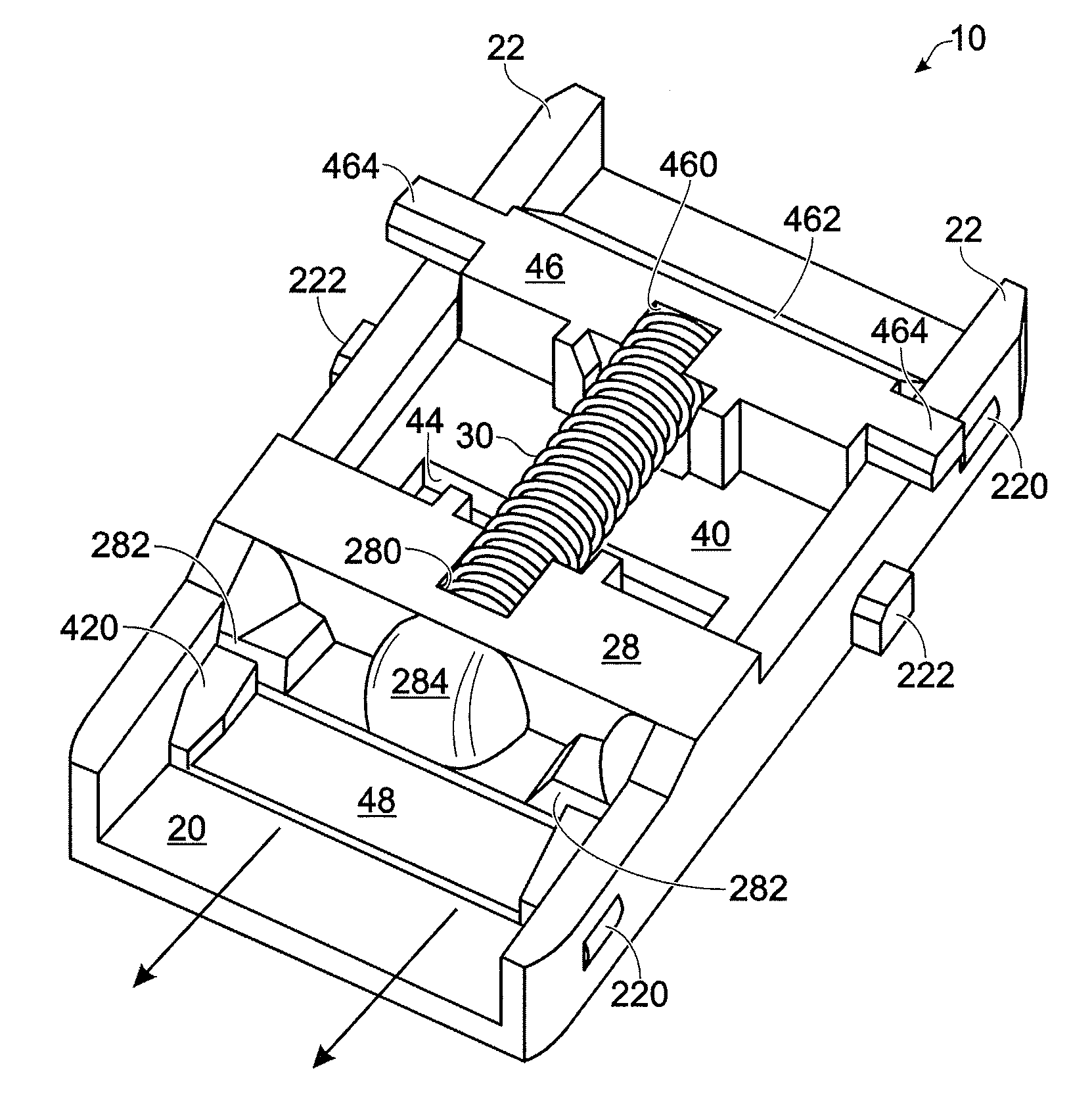
[0042]Reference will now be made in detail to the present exemplary embodiments of the invention, examples of which are illustrated in the accompanying drawings. Wherever possible, the same reference numbers will be used throughout the drawings to refer to the same or like parts. An exemplary embodiment of the protective shutter assembly of the present invention is shown in FIG. 1, and is designated generally throughout by reference numeral 10.

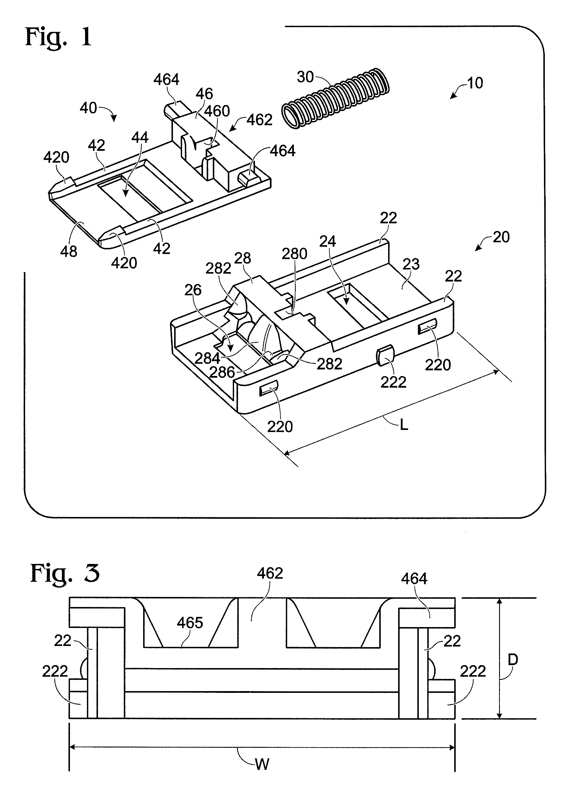
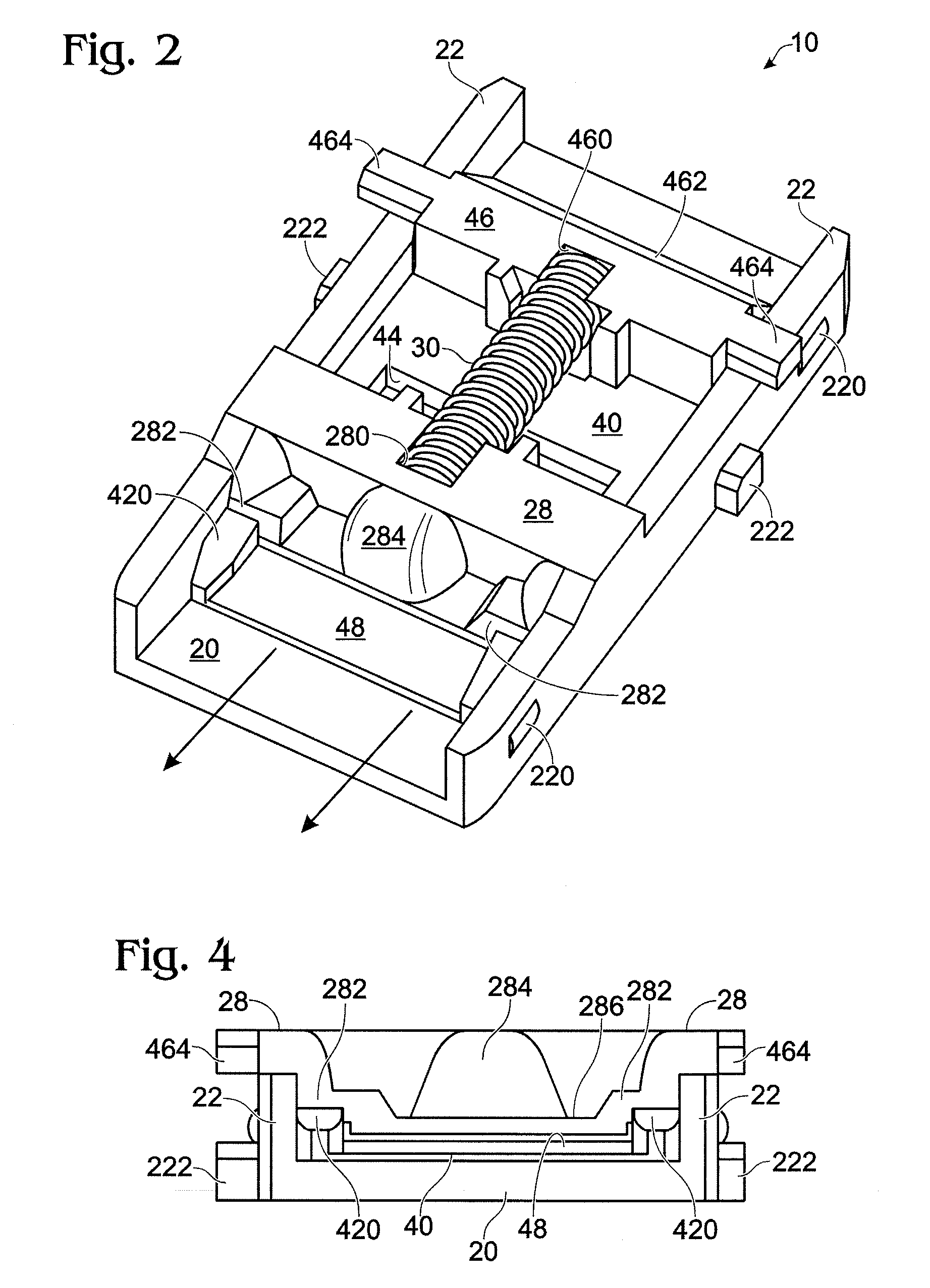
[0043]As embodied herein and depicted in FIG. 1, an exploded view of a protective shutter assembly 10 in accordance with one embodiment of the present invention is disclosed. The protective shutter assembly 10 is a frameless mechanism that includes a lower shutter member 20 and an upper shutter member 40. A spring member 30 is disposed between lower shutter 20 and upper shutter 40.

[0044]The lower shutter 20 includes side rails 22 and a base member 23 disposed therebetween. Base 23 has a first hot contact aperture 26 and a neutral contact apert...


PUM


Abstract

The present invention is directed to a protective shutter assembly for use within a cover assembly of an electrical wiring device. The assembly includes a frameless shutter sub-assembly movable between a closed position and an open position. The frameless shutter sub-assembly is configured to move from the closed position to the open position in response to engaging at least one plug blade having a predetermined plug blade geometry. A spring member is disposed within the frameless shutter sub-assembly. The spring member is configured to bias the frameless shutter sub-assembly in the closed position. At least one retainer element is disposed in the frameless shutter sub-assembly. The at least one retainer element being configured to retain the spring member within the frameless shutter sub-assembly. At least one registration member is disposed on the frameless shutter sub-assembly, the at least one registration member being configured to position and align the protective shutter assembly within the cover assembly.

Description

CROSS-REFERENCE TO RELATED APPLICATIONS[0001]This is a continuation-in-part of U.S. patent application Ser. No. 10 / 900,778 entitled “A Protective Device with Tamper Resistant Shutters” filed on Jul. 28, 2004, now U.S. Pat. No. 7,179,992 which is a continuation-in-part of U.S. patent application Ser. No. 10 / 729,685 entitled “A Protective Device with Tamper Resistant Shutters” filed on Dec. 5, 2003, the contents of which are relied upon and incorporated herein by reference in their entirety, and the benefit of priority under 35 U.S.C. § 120 is hereby claimed.BACKGROUND OF THE INVENTION[0002]1. Field of the Invention[0003]The present invention relates generally to electrical protection devices, and particularly to electrical protection devices with safety features.[0004]2. Technical Background[0005]As those of ordinary skill in the art understand, an electric circuit comprises many different electrical wiring devices disposed at various locations throughout a structure. These devices i...

Claims


Application Information

Patent Timeline
Patent Type & Authority Patents(United States)
IPC IPC(8): H01R13/46
CPCH01R13/4534
Inventor WEEKS, RICHARDRADOSAVLJEVIC, DEJANPACKARD, THOMAS N.THIBAULT, STEVEN C.
Owner PASS SEYMOUR
Why Eureka
Try Eureka