
Telecommunications patching system with patching modules

a technology of patching module and telecommunications equipment, applied in the field of high-density fiber distribution apparatus, can solve problems such as affecting the desirable management of cable and cords, and hampering cable management practices

Inactive Publication Date: 2010-03-02
COMMSCOPE INC
View PDF15 Cites 82 Cited by
  • Summary
  • Abstract
  • Description
  • Claims
  • Application Information

AI Technical Summary

Benefits of technology

[0010]As a fourth aspect, embodiments of the present invention are directed to a telecommunications patching system, comprising: a first vertical stack of patching modules, wherein each of the patching modules include a plurality of connectors on a first side thereof; and a second vertical stack of patching modules positioned laterally from the first side of the first vertical stack of patching modules, wherein the vertical distance between at least some adjacent patching modules of the second vertical stack of patching modules exceeds the vertical distance between adjacent patching modules of the second vertical stack of patching modules.
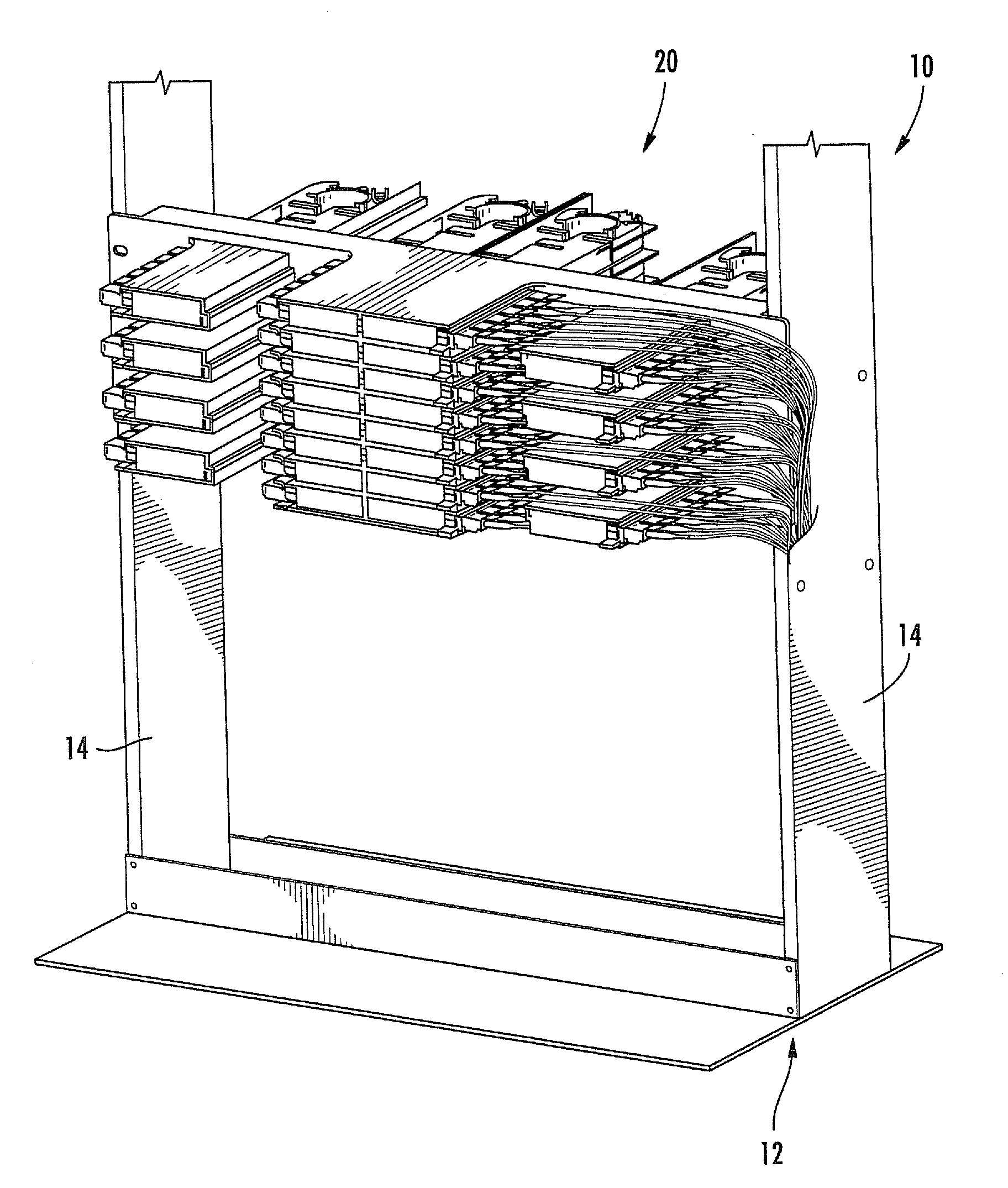
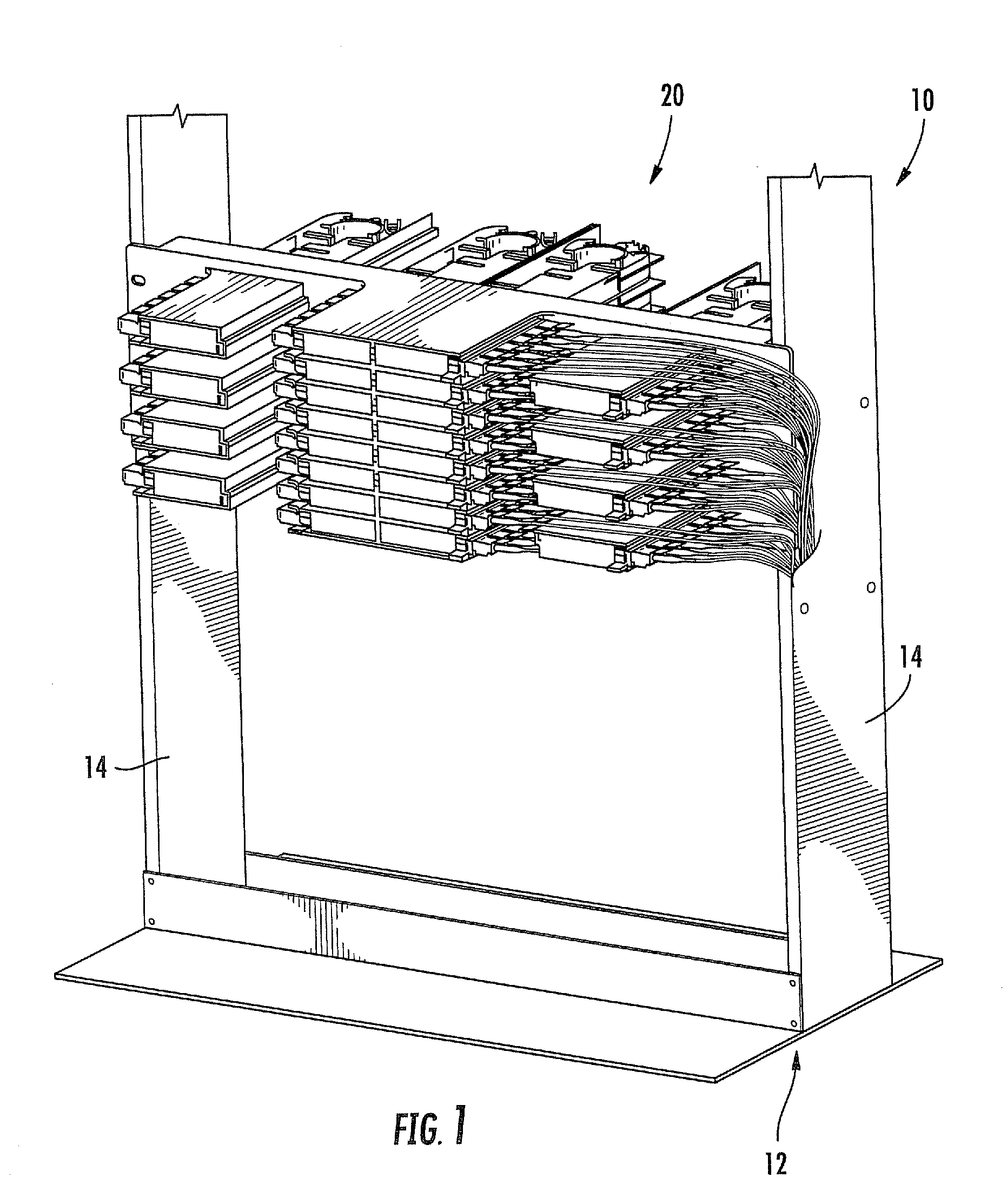
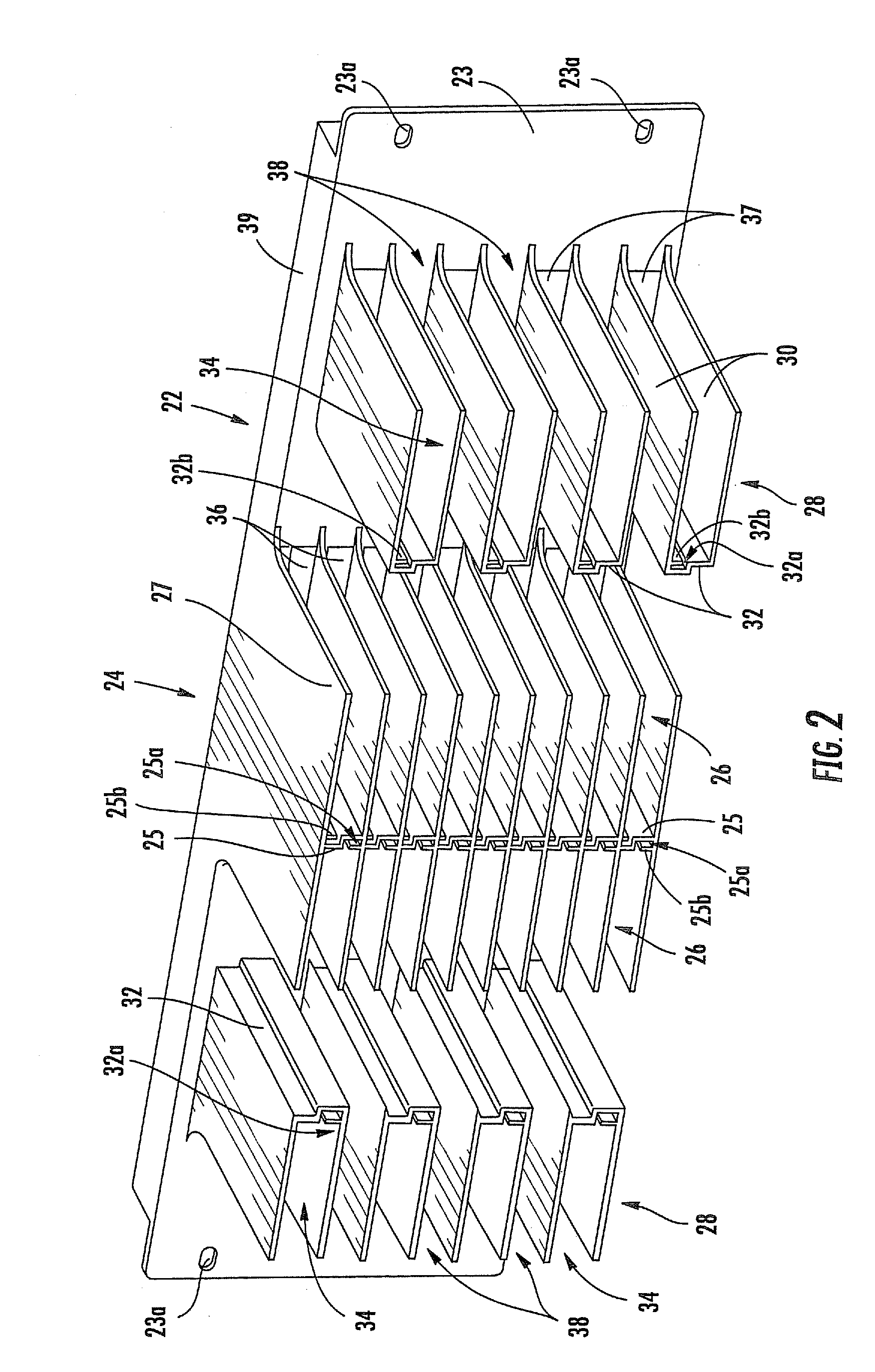
[0008]As a second aspect, embodiments of the present invention are directed to a telecommunications patching system, comprising: a rear panel, the rear panel including a plurality of cutout areas; a series of central compartments mounted to the rear panel, the central compartments being disposed in adjacent, vertically stacked relationship in at least one column, the rear ends of the central compartments being aligned with at least one of the cutout areas; and at least one series of lateral compartments mounted to the rear panel, the lateral compartments being disposed in spaced apart, vertically stacked relationship and laterally positioned from the central compartments, the rear ends of the lateral compartments being aligned with at least one of the cutout areas. The system also includes at least one central patching module with a plurality of connectors, the central patching module residing in one of the central compartments, the plurality of connectors being oriented to receive a communications cable from a lateral direction, a rear end of the central patching module extending rearwardly through a respective one of the cutout areas; and at least one lateral patching module with a plurality of connectors, the lateral patching module residing in one of the lateral compartments, the plurality of connectors being oriented to receive a communication cable from a lateral direction, a rear end of the lateral patching module extending rearwardly through a respective one of the cutout areas.
[0009]As a third aspect, embodiments of the present invention are directed to a telecommunications assembly, comprising: a mounting rack; and at least one telecommunications patching system. The patching system comprises: a rear panel, the rear panel including a plurality of cutout areas; a series of central compartments mounted to the rear panel, the central compartments being disposed in adjacent, vertically stacked relationship in at least one column, the rear ends of the central compartments being aligned with the cutout areas; and at least one series of lateral compartments mounted to the rear panel, the lateral compartments being disposed in spaced apart, vertically stacked relationship and laterally positioned from the central compartments, the rear ends of the lateral compartments being aligned with the cutout areas. The patching system further comprises at least one central patching module with a plurality of connectors, the central patching module residing in one of the central compartments, the central patching module having a plurality of connectors oriented to receive a communications cable from a lateral direction, a rear end of the central patching module extending rearwardly through the cutout area; and at least one lateral patching module with a plurality of connectors, the lateral patching module residing in one of the lateral compartments, the lateral patching module having a plurality of connectors oriented to receive a communication cable from a lateral direction, a rear end of the lateral patching module extending rearwardly through the cutout area.
[0010]As a fourth aspect, embodiments of the present invention are directed to a telecommunications patching system, comprising: a first vertical stack of patching modules, wherein each of the patching modules include a plurality of connectors on a first side thereof; and a second vertical stack of patching modules positioned laterally from the first side of the first vertical stack of patching modules, wherein the vertical distance between at least some adjacent patching modules of the second vertical stack of patching modules exceeds the vertical distance between adjacent patching modules of the second vertical stack of patching modules.

Problems solved by technology

The space constraints associated with high-density distribution frames can cause cable and cord management problems.
However, increased density can hamper desirable cable management practices.

Method used


Image

  • Telecommunications patching system with patching modules
  • Telecommunications patching system with patching modules
  • Telecommunications patching system with patching modules

Examples


Embodiment Construction

[0018]The present invention will be described more particularly hereinafter with reference to the accompanying drawings. The invention is not intended to be limited to the illustrated embodiments; rather, these embodiments are intended to fully and completely disclose the invention to those skilled in this art. In the drawings, like numbers refer to like elements throughout. Thicknesses and dimensions of some components may be exaggerated for clarity.

[0019]Unless otherwise defined, all terms (including technical and scientific terms) used herein have the same meaning as commonly understood by one of ordinary skill in the art to which this invention belongs. It will be further understood that terms, such as those defined in commonly used dictionaries, should be interpreted as having a meaning that is consistent with their meaning in the context of the relevant art and will not be interpreted in an idealized or overly formal sense unless expressly so defined herein.

[0020]In addition, ...


PUM


Abstract

A telecommunications patching system includes: a rear panel, the rear panel including a plurality of cutout areas; a series of central compartments mounted to the rear panel, the central compartments being disposed in adjacent, vertically stacked relationship in at least one column, the rear ends of the central compartments being aligned with at least one of the cutout areas; and at least one series of lateral compartments mounted to the rear panel, the lateral compartments being disposed in spaced apart, vertically stacked relationship and laterally positioned from the central compartments, the rear ends of the lateral compartments being aligned with at least one of the cutout areas. The system also includes at least one central patching module with a plurality of connectors, the central patching module residing in one of the central compartments, the plurality of connectors being oriented to receive a communications cable from a lateral direction, a rear end of the central patching module extending rearwardly through a respective one of the cutout areas; and at least one lateral patching module with a plurality of connectors, the lateral patching module residing in one of the lateral compartments, the plurality of connectors being oriented to receive a communication cable from a lateral direction, a rear end of the lateral patching module extending rearwardly through a respective one of the cutout areas.

Description

RELATED APPLICATIONS[0001]This is a continuation-in-part application of and claims the benefit of priority from U.S. patent application Ser. No. 12 / 244,189 filed Oct. 2, 2008 now abandoned, the disclosure of which is incorporated herein by reference in its entirety.FIELD OF THE INVENTION[0002]The present invention relates generally to telecommunications equipment, and more particularly to high-density fiber distribution apparatus.BACKGROUND OF THE INVENTION[0003]In the telecommunications industry, the use of fiber optic cables for carrying transmission signals is rapidly growing. To interconnect fiber optic equipment, fiber distribution frames and racks have been developed. Such frames and racks are typically located in a communications closet, data room, or the like, where technicians can easily connect and reconnect, or “patch,” equipment in an organized and efficient manner. Examples of fiber distribution frames and racks are shown in U.S. Pat. Nos. 5,497,444 and 5,758,003, which...

Claims


Application Information

Patent Timeline
IPC IPC(8): G02B6/00G02B6/36
CPCH04Q1/06H04Q1/023H04Q1/13G02B6/4452H04Q2201/04G02B6/3897H04Q1/14H04Q1/141
Inventor KEITH, SCOTT MARTINCHOI-FENG, CHINCHOUDHURY, GOLAM MABUDCONORICH, THEODORE ALAN
Owner COMMSCOPE INC
Learn More