Electrokinetic micro power cell using microfluidic-chip with multi-channel type
a microfluidic chip and micro-power cell technology, applied in the direction of fuel cells, diaphragms, immobilised enzymes, etc., can solve the problems of power cell relevance, low surface potential of 1:1 type electrolyte solution, and insufficient development, so as to achieve efficient electrical energy.
- Summary
- Abstract
- Description
- Claims
- Application Information
AI Technical Summary
Benefits of technology
Problems solved by technology
Method used
Image
Examples
embodiment 1
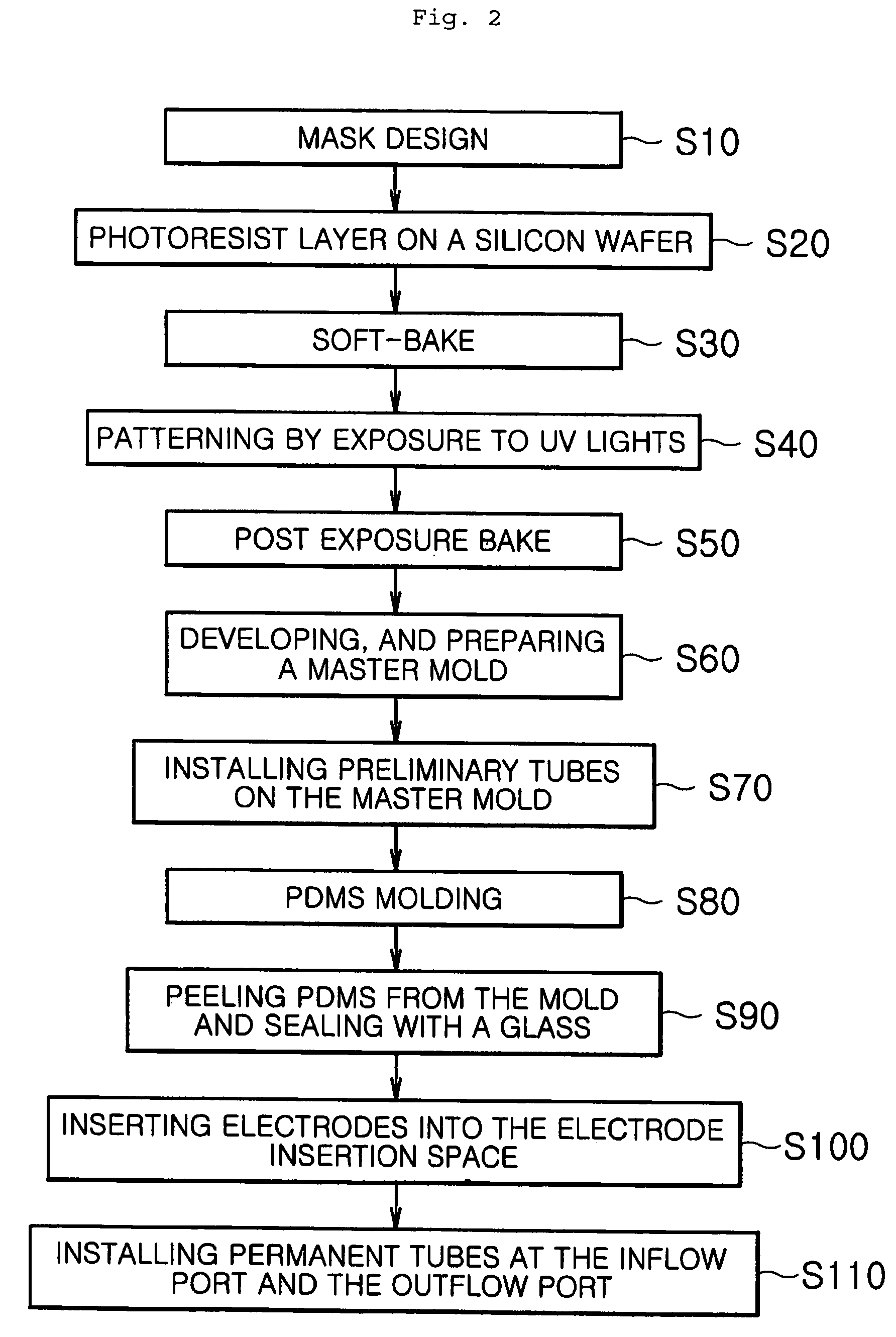
Fabrication of Master Mold for Making a Microfluidic-Chip Device with a Multi-Channel Type According to the Invention
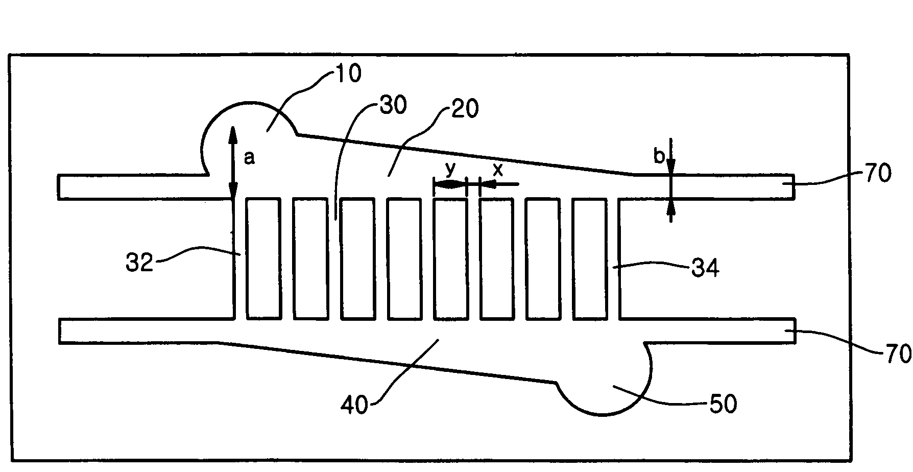
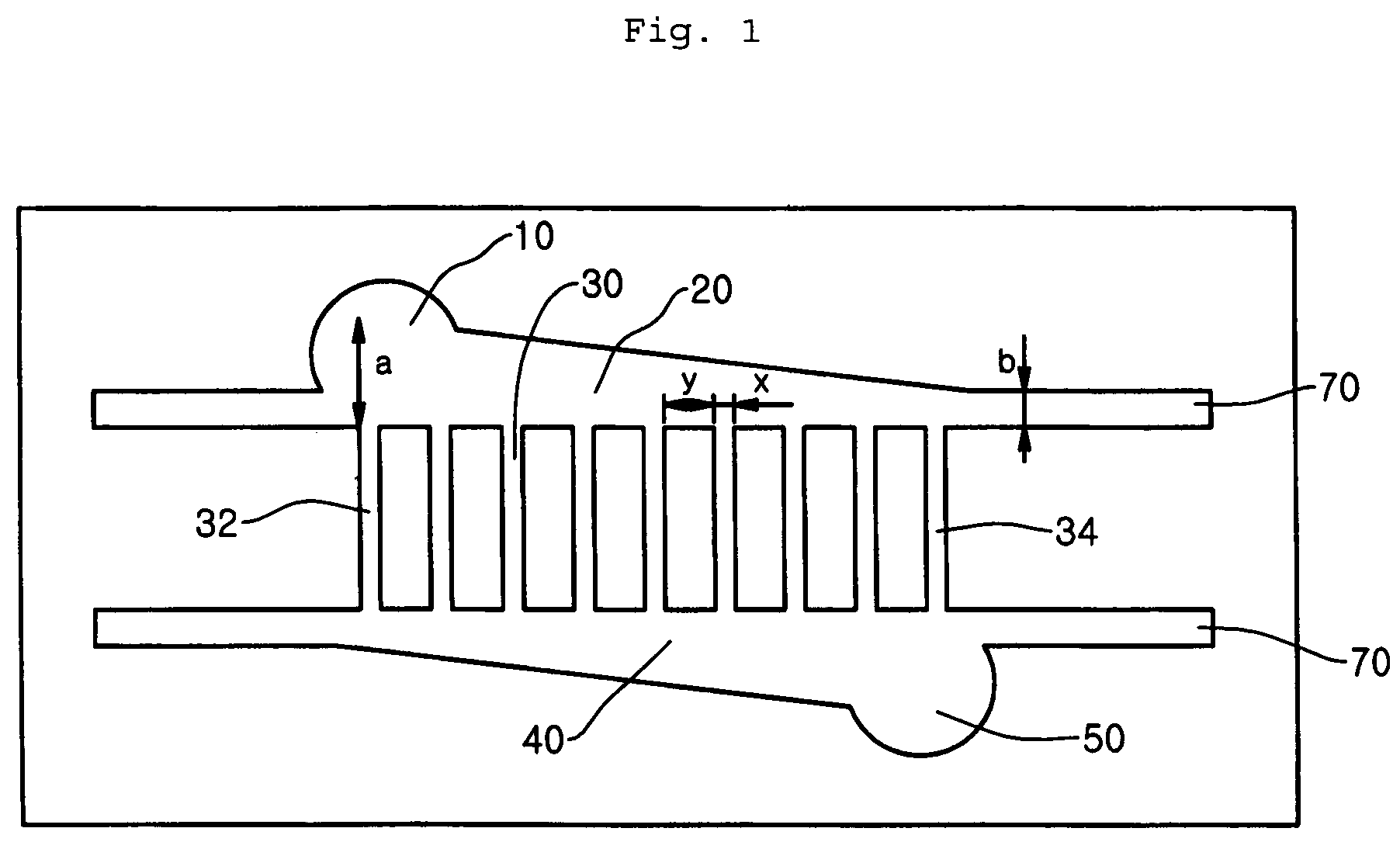
[0068]FIG. 1 depicts a photomask drawing designed by AutoCAD® 2002 as a first step for making the microfluidic-chip according to the invention. The chip includes the inflow port 10, the distributor 20, the multi-channel 30, the collector 40, and the outflow port 50.
[0069]In the distributor 20 and the collector 40, Ag / AgCl electrodes should be inserted. Therefore, the distributor 20 and the collector 40 should be formed in the depth enough to place the electrodes in them. Similarly, the multi-channel 30 consisting of 100 microchannels should be formed to the same depth as the distributor 20 and the collector 40. Because the diameter of conventional electrodes has about 100 μm, it is optimum to form the microchannel depth to be about 100 μm.
[0070]The diameter of the inflow port 10 into which fluid flows and the outflow port 50 from which fluid flows out may be determine...
embodiment 2
Fabrication of a Streaming Potential Cell
[0095]Before inserting electrodes, an Ag wire (Aldrich Chemical Co., WI) with 100 μm diameter to use as the electrode is washed in 3M HNO3 solution for 5 minutes. Then, the anode (red color) of a power supply is connected to the Ag wire and the cathode (black color) is connected to a Pt wire in 0.1M HCl solution, and then, 4 mA / cm2 of static current is applied for 20 minutes to anodize. AgCl coats the surface of Ag wire, and then an Ag / AgCl electrode can be prepared.
[0096]The Ag / AgCl electrodes are inserted into the electrode insertion space 70 of the microfluidic-chip of the invention.
[0097]Cutting both ends of the PDMS replica peeled from the master mold gives to form holes at both ends of the electrode insertion space in 300 μm width and 100 μm depth. After that, an electrode is inserted into the hole, and the electrode is protruded outside from both ends of the electrode insertion space. Then, the Ag / AgCl electrode is connected to an exte...
embodiment 3
Measurement Experiments for Electric Potential with a Micro Power Cell According to the Invention
[0103]As shown in FIG. 5, a streaming potential cell is comprised in an electrokinetic micro power cell. In FIG. 5, the fluid that is electrolyte solution contained in a reservoir is supplied into the inflow port 10 by a high-precision metering pump (SD-200, Rainin, Calif.), and it is drained to the outflow port 50 after flowing through the multi-channel 30. The pressure difference ΔP between both ends of microchannels 30 is measured by a precise pressure gauge. The streaming potential difference ΔE between both ends of channels is measured by a digital multi-meter (HP34970A, Hewlett-Packard Co., CA) via the Ag / AgCl electrodes 60 placed respectively at upper and lower parts of the channels. By having electrolyte solution with various ionic concentrations flow, the streaming potential is measured.
[0104]FIG. 9 depicts results of the streaming potential generated depending on the channel wi...
PUM
| Property | Measurement | Unit |
|---|---|---|
| length | aaaaa | aaaaa |
| length | aaaaa | aaaaa |
| depth | aaaaa | aaaaa |
Abstract
Description
Claims
Application Information
 - R&D
- Intellectual Property
- Life Sciences
- Materials
- Tech Scout
- Unparalleled Data Quality
- Higher Quality Content
- 60% Fewer Hallucinations
Browse by: Latest US Patents, China's latest patents, Technical Efficacy Thesaurus, Application Domain, Technology Topic, Popular Technical Reports.
© 2025 PatSnap. All rights reserved.Legal|Privacy policy|Modern Slavery Act Transparency Statement|Sitemap|About US| Contact US: help@patsnap.com


