Solar heating system and architectural structure with a solar heating system

a solar heating and solar energy technology, applied in ventilation systems, heating types, lighting and heating apparatus, etc., can solve the problems of ineffective use inability to optimize the southern-facing side wall orientation of collectors established during building construction, and difficulty in achieving the effect of conventional solar heating systems

Active Publication Date: 2010-03-16
WALMART APOLLO LLC
View PDF73 Cites 25 Cited by
  • Summary
  • Abstract
  • Description
  • Claims
  • Application Information

AI Technical Summary

Problems solved by technology

However, the orientation of the southern-facing side wall of building established during construction of building may not be optimized to orient the collector relative to the track of the sun across the sky during daylight hours.
Such conventional solar heating systems are also problematic if the southern-facing side wall is used as a building entrance, a loading dock, etc.
Although shorter buildings may lack a large-area southern-facing wall, their roofs may have a substantial surface area that cannot be effectively utilized by conventional solar heating systems.

Method used


Image

  • Solar heating system and architectural structure with a solar heating system
  • Solar heating system and architectural structure with a solar heating system
  • Solar heating system and architectural structure with a solar heating system

Examples


Embodiment Construction

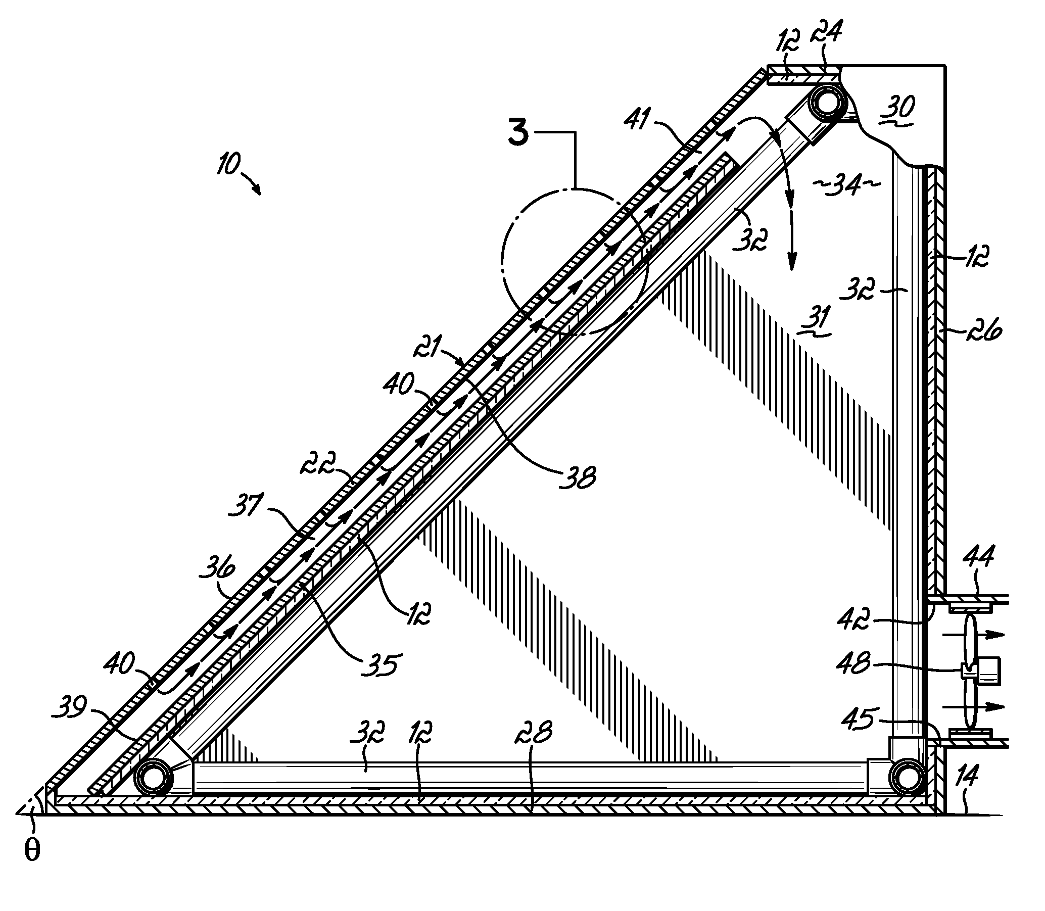
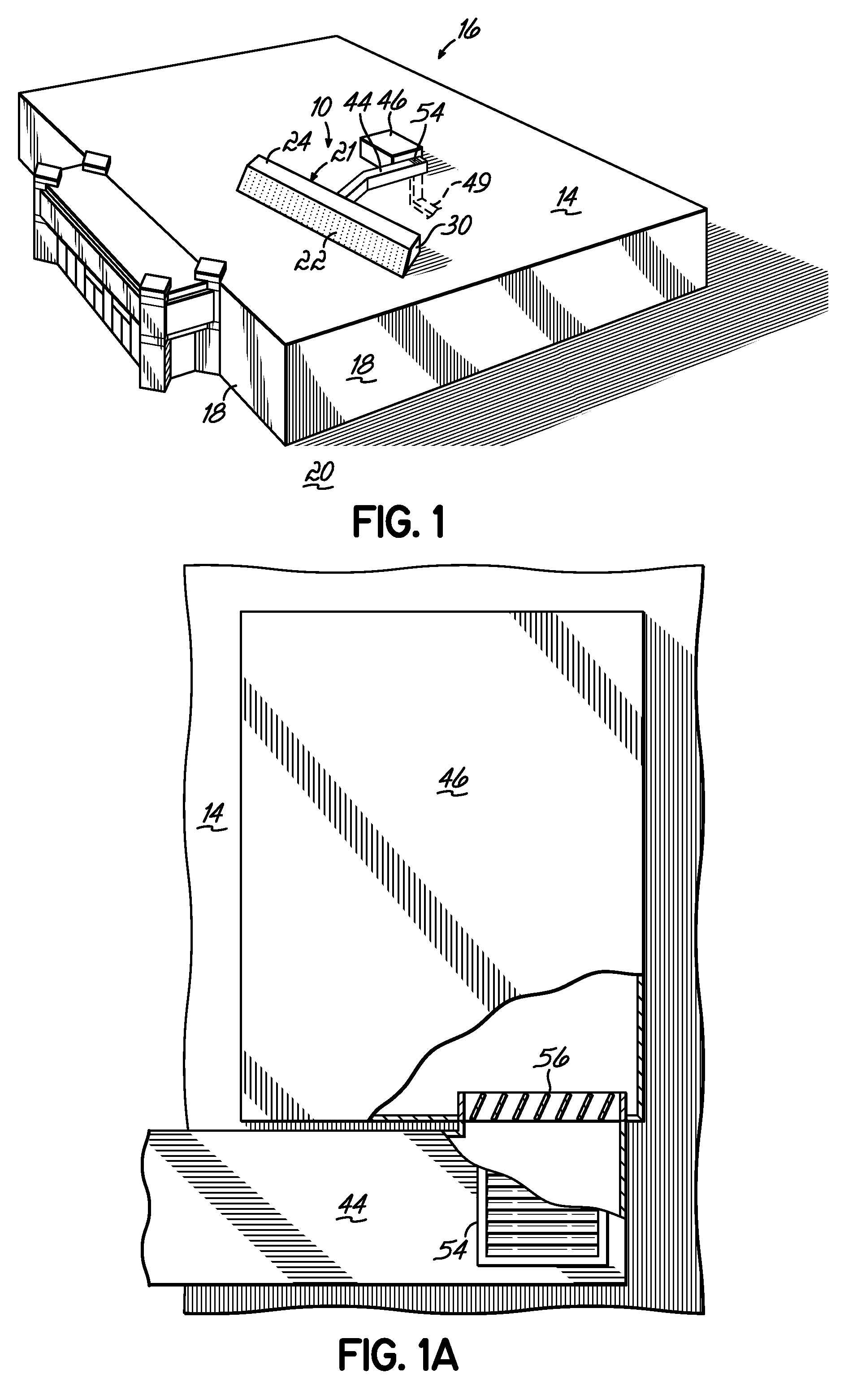
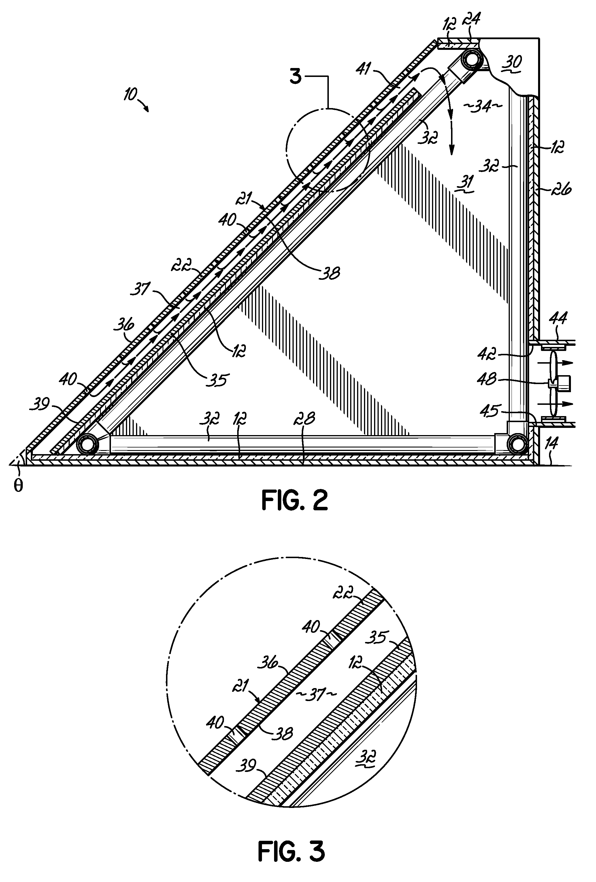
[0018]With reference to FIG. 1, a solar heating module 10 is situated on a roof 14 of a building 16. The roof 14 may have a substantially greater surface area than exterior side walls 18 of the building 16 that extend from roof 14 to a ground surface 20 and encircle the perimeter of the building 16. The roof 14 is represented as substantially flat and planar, although the roof 14 may also be pitched or otherwise non-planar to, for example, promote water drainage. The side walls 18 may incorporate a building entrance, a loading dock, windows, etc. The solar heating module 10 may be secured to the roof 14 using a conventional method known to a person having ordinary skill in the art. The space enclosed by the roof 14 and side walls 18 of building 16 may be used, for example, to conduct commercial activities, such as retail product sales, and other activities apparent to a person having ordinary skill in the art. Alternatively, the space enclosed inside building 16 may be used for non-...


PUM


Abstract

A solar heating system for a building and other architectural structures including a solar heating system. The solar heating system comprises a solar heating module with an enclosure of panels bounding a plenum. An interior panel is disposed inside the enclosure. A collector panel, which is separated from the interior panel to define a heating chamber, is exposed to, and heated by, solar radiation. Outside air enters the heating chamber though passages in the collector panel, where the air is heated by heat transferred from the collector panel. An air-moving device is coupled with an air outlet from the plenum. The air-moving device applies a negative pressure in the heating chamber effective for drawing the outside air through the passages into the heating chamber and for withdrawing the heated air from the heating chamber through a delivery opening to the plenum for subsequent removal through the air outlet.

Description

FIELD OF THE INVENTION[0001]The invention generally relates to solar heating devices and, more particularly, relates to solar heating systems and architectural structures with solar heating systems.BACKGROUND OF THE INVENTION[0002]Solar heating harnesses solar radiation emitted by the sun to provide solar thermal energy for various different domestic and commercial uses including solar hot water, solar space heating, and solar pool heaters. Among their attributes, solar heating systems conserve energy, reduce utility costs, and produce clean energy. Generally, solar heating systems convert solar radiation into usable or sensible heat. To that end, many conventional solar heating systems utilize a large area collector for absorbing heat from the solar radiation. The absorbed sensible heat is transferred to a fluid, which is subsequently transferred to the ventilated space inside a building.[0003]Conventional solar heating systems may be integrated as a cladding directly into a southe...

Claims


Application Information

Patent Timeline
Patent Type & Authority Patents(United States)
IPC IPC(8): E04D13/18F24J2/00
CPCF24F5/0046F24J2/0488F24J2/20F24F2005/0064Y02B10/20Y02B10/24Y02E10/44F24S10/50F24S70/60Y02A30/272
Inventor MCCLENDON, JAMES PATRICK
Owner WALMART APOLLO LLC
Why Eureka
Try Eureka