Patch-like infusion device

a technology of infusion device and substance, which is applied in the field of substance delivery device, can solve the problems of high initial cost of the pump, limited lifetime, and high cost (roughly 8 to 10 times the daily cost of syringe therapy), and achieve the effects of reducing or eliminating variations in injection technique, facilitating self-injection, and preventing accidental activation

Inactive Publication Date: 2010-03-16
BECTON DICKINSON & CO
View PDF57 Cites 168 Cited by
  • Summary
  • Abstract
  • Description
  • Claims
  • Application Information

AI Technical Summary

Benefits of technology

[0008]An object of the present invention is to provide a patch-like infusion device which can be conveniently worn against the skin while providing infusion of a desired substance.

Problems solved by technology

The initial cost of the pump is a high barrier to this type of therapy.
However, in addition to their high cost (roughly 8 to 10 times the daily cost of syringe therapy) and limited lifetime, insulin pumps represent relatively old technology and are cumbersome to use.
Also, from a lifestyle standpoint, the tubing (known as the “infusion set”) that links the pump with the delivery site on the user's abdomen is very inconvenient and the pumps are relatively heavy, making carrying the pump a bother.
However, patients on oral agents eventually move to insulin, and existing pump therapy is very expensive.
Unfortunately, however, many of these devices suffer from disadvantages including user discomfort (due to the gauge and / or length of injection needle used), compatibility and interaction between the substance being delivered and the materials used in the construction of the infusion device, and possible malfunctioning if not properly activated by the user (e.g., “wet” injections resulting from premature activation of the device.
Difficulties in manufacturing and in controlling needle penetration depth have also been encountered, particularly when short and / or fine-gauge injection needles are used, and the possibility of causing needle-stick injuries to those who come into contact with the used device has also been problematic.

Method used


Image

  • Patch-like infusion device
  • Patch-like infusion device
  • Patch-like infusion device

Examples


second embodiment

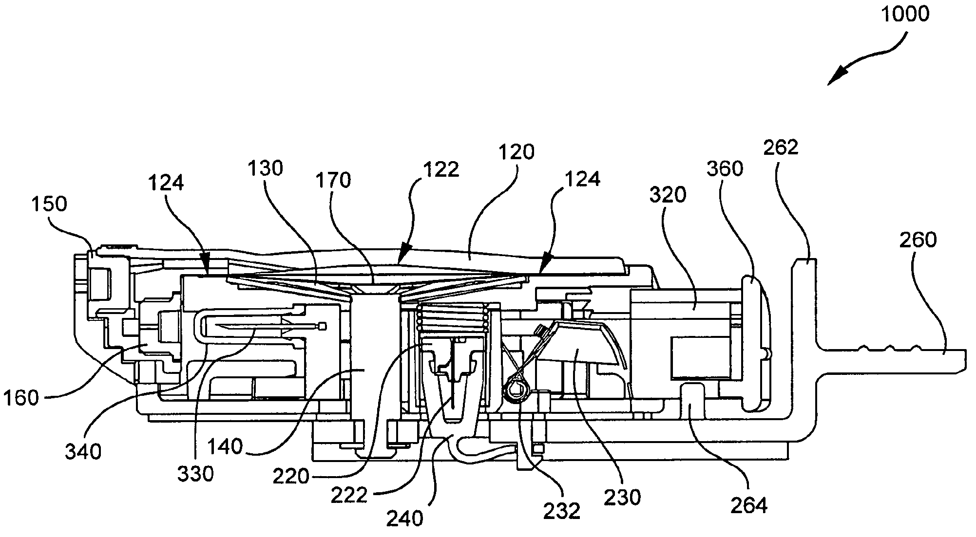
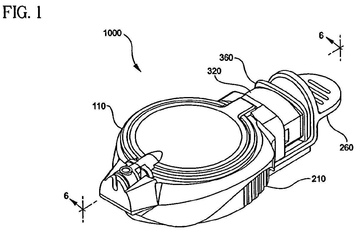
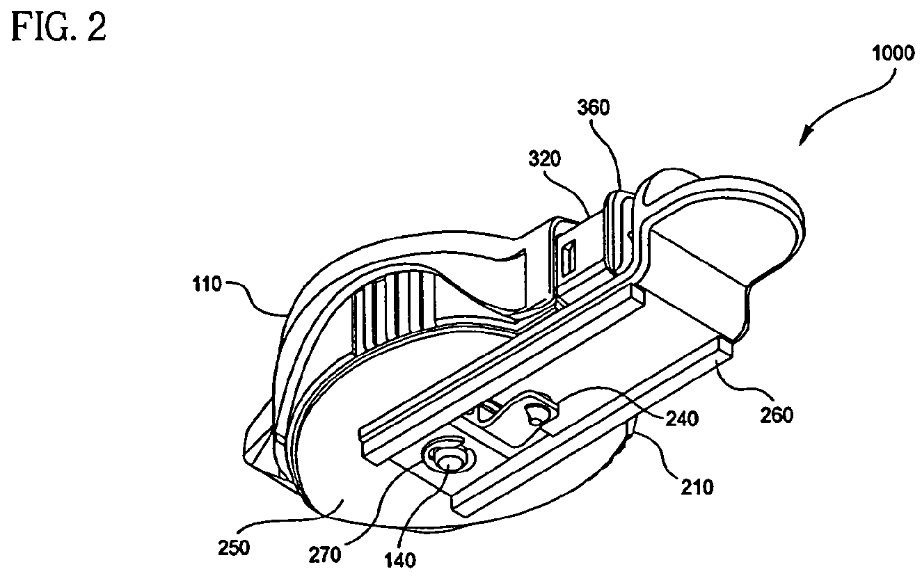
[0166]A second embodiment of the device, shown in FIGS. 19A and 19B, is a push-button design 400 wherein the activation and energizing of the device is accomplished in a single multi-function / step process. FIG. 19A is an exploded perspective view of a second embodiment of a patch-like injector or infuser system using a side push button, FIG. 19B is a cross-sectional view of the patient needle / septum needle manifold system of the second embodiment, FIG. 19C is a cross-sectional view of the second embodiment shown in FIG. 19A prior to energizing and activation, and FIG. 19D is a cross-sectional view of the second embodiment shown in FIG. 19A after energizing and activation.

[0167]The device of FIGS. 19A through 19D includes a top housing 410 and rigid bottom 415, a spring lock pin 420, a push button 430, a manifold 440, a Belleville spring 460, and a reservoir lid 480. The manifold 440 further includes one or more patient needles 442 and at least one septum needle 444 to pierce a septu...

third embodiment

[0170]A third embodiment of the device, shown in FIGS. 20A through 20C, is a push-button design 500 wherein the bladder itself moves towards the patient's skin and contacts a manifold having both the patient needles and the septum needle (positioned in opposite directions), and forces the patient needles into the patient's skin, and the septum needle into the septum. FIG. 20A is an exploded perspective view of a third embodiment of a patch-like injector or infuser system using a side push button, FIG. 20B is a cross-sectional view of the third embodiment shown prior to energizing and activation and FIG. 20C is a cross-sectional view of the third embodiment shown after energizing and activation.

[0171]The device of FIGS. 20A through 20C includes a pull pin handle 505, a top housing 510, a leaf spring 520, a reservoir top 525, a Belleville spring 530, a reservoir lid 535, a reservoir bottom 540, a septum 545, a manifold system 550, a push button 555, a bottom housing 560, a safety clip...

fourth embodiment

[0174]A fourth embodiment of the device, shown in FIGS. 21A through 21C, is a push-button design wherein the push-button is located on the top, outer surface of the device, and the user energizes and activates the fluid flow by depressing the button to its lower-most position. FIG. 21A is an exploded perspective view of a fourth embodiment of a patch-like injector or infuser system using a top push button, FIG. 21B is a partial cross-sectional view of the fourth embodiment shown in FIG. 21A prior to energizing and activation, and FIG. 21C is partial cross-sectional view of the fourth embodiment shown in FIG. 21A after energizing and activation.

[0175]The device of FIG. 21A includes a top push button 602, an upper housing 605, leaf springs 610, a manifold assembly 615, pull pin 620, release guide 630, retainer 635, Belleville spring 640 and reservoir 645. As with the earlier embodiments described above, the adhesive 655 and 660 on the bottom surface of the device is exposed and the us...


PUM


Abstract

A system and method for a patch-like, self-contained substance infusion device which provides one or more substantially hidden patient needles which can be placed in fluid communication with a fluid reservoir subassembly that includes a rigid bladder portion used in conjunction with a non-distensible bladder film, such as a metallized film. Simple removal of an interlock allows a disk, or Belleville spring assembly to apply an essentially even and constant pressure to the contents of the fluid reservoir assembly, and allows the device to then be attached to a skin surface via an adhesive contact surface. A push button activation assembly is provided which can then be used to release and seat one or more spring-loaded patient needles into the skin surface, and establish a fluid communication path between the patient needles and the pressurized fluid reservoir contents thereby delivering an infusion into the skin.

Description

CROSS-REFERENCE TO RELATED APPLICATIONS[0001]This application is a continuation of U.S. application Ser. No. 10 / 623,702, filed Jul. 22, 2003 now U.S. Pat. No. 7,250,037 which claimed benefit under 35 U.S.C. §119(e) from U.S. provisional patent application Ser. No. 60 / 397,038, entitled “Patch-Like Infusion Device”, filed on Jul. 22, 2002; from U.S. provisional patent application Ser. No. 60 / 407,284, entitled “Patch-Like Infusion Device”, filed on Sep. 3, 2002; from U.S. provisional patent application Ser. No. 60 / 420,233, entitled “Patch-Like Infusion Device”, filed on Oct. 23, 2002; from U.S. provisional patent application Ser. No. 60 / 447,359, entitled “Patch-Like Infusion Device”, filed on Feb. 14, 2003; from U.S. provisional patent application Ser. No. 60 / 450,680, entitled “Patch-Like Infusion Device”, filed on Mar. 3, 2003; and from U.S. provisional patent application Ser. No. 60 / 450,681, entitled “Patch-Like Infusion Device”, filed on Mar. 3, 2003; the entire content of each of s...

Claims


Application Information

Patent Timeline
Patent Type & Authority Patents(United States)
IPC IPC(8): A61M5/20A61M37/00A61MA61M5/142A61M5/145A61M5/148A61M31/00
CPCA61M5/142A61M5/14248A61M5/148A61M5/145A61M2005/14252A61M2005/1426A61M2005/14268A61M2005/14506
Inventor SHERMER, CHARLES D.POWELL, KENNETH G.LASTOVICH, ALEXANDER G.KINSEY, P. SPENCERSMUTNEY, CHAD C.POLIDORO, JOHN M.BROWKA, EDSAHI, CARL R.FENTRESS, JAMES K.CHAPIN, DAVID S.STIPE, DANIELMOSS, JEFF M.KURODA, MELODY
Owner BECTON DICKINSON & CO
Why Eureka
Try Eureka