This helps you quickly interpret patents by identifying the three key elements:
Problems solved by technology
Method used
Benefits of technology
Benefits of technology
[0009] An object of the present invention is to provide a patch-like infusion device which can be conveniently worn against
Problems solved by technology
The initial cost of the pump is a high barrier to this type of therapy.
However, in addition to their high cost (roughly 8 to 10 times the daily cost of syringe therapy) and limited lifetime, insulin pumps represent relatively old technology and are cumbersome to use.
Also, from a lifestyle standpoint, the tubing (known as the “infusion set”) that links the pump with the delivery site on the user's abdomen is very inconvenient and the pumps are relatively heavy, making carrying the pump a burden.
Unfortunately, however, many of these devices suffer from disadvantages including user discomfort (due to the g
Method used
Image
Click on the blue label to locate the original text in one second.
Reading with bidirectional positioning of images and text.
Examples
Example
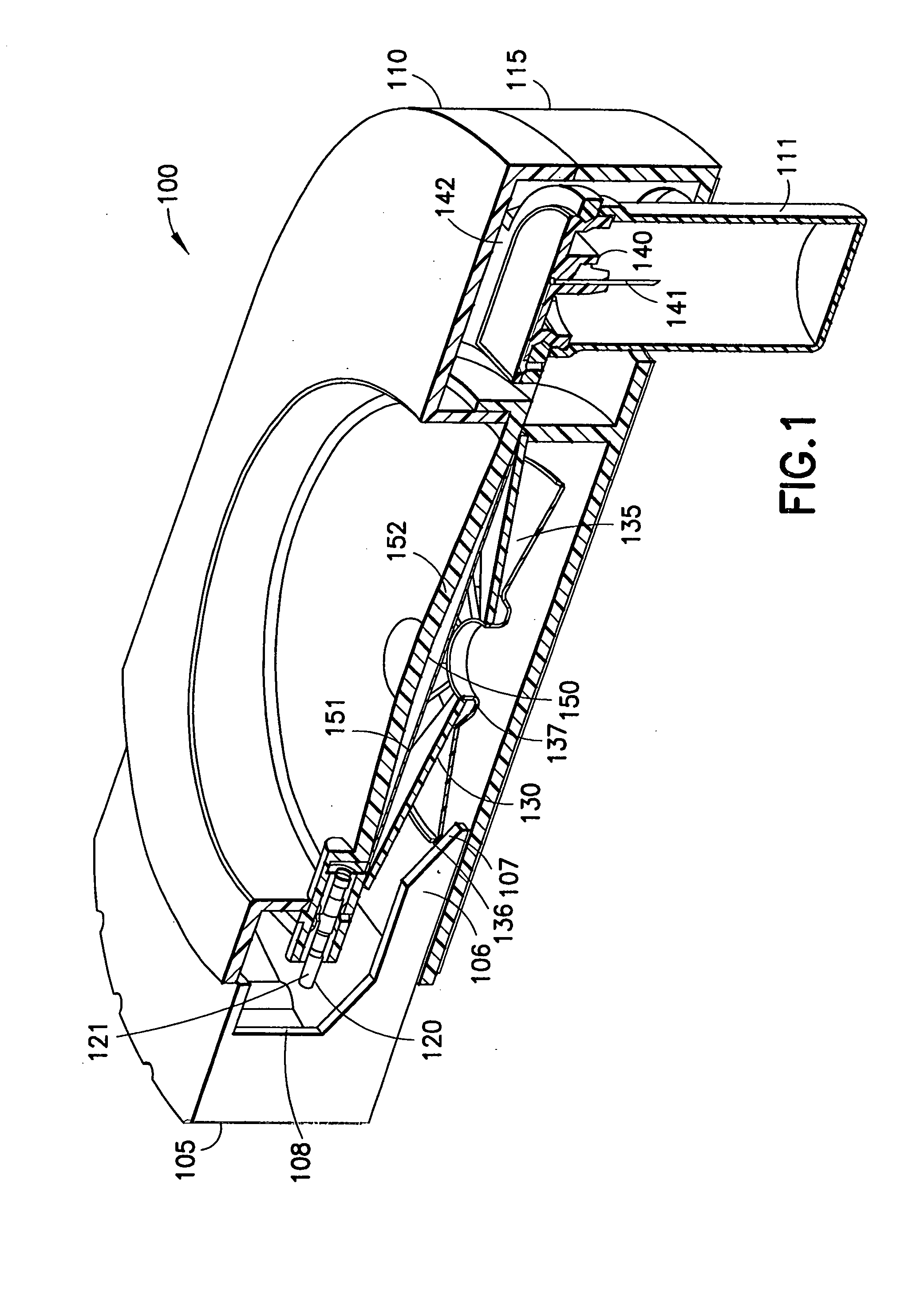
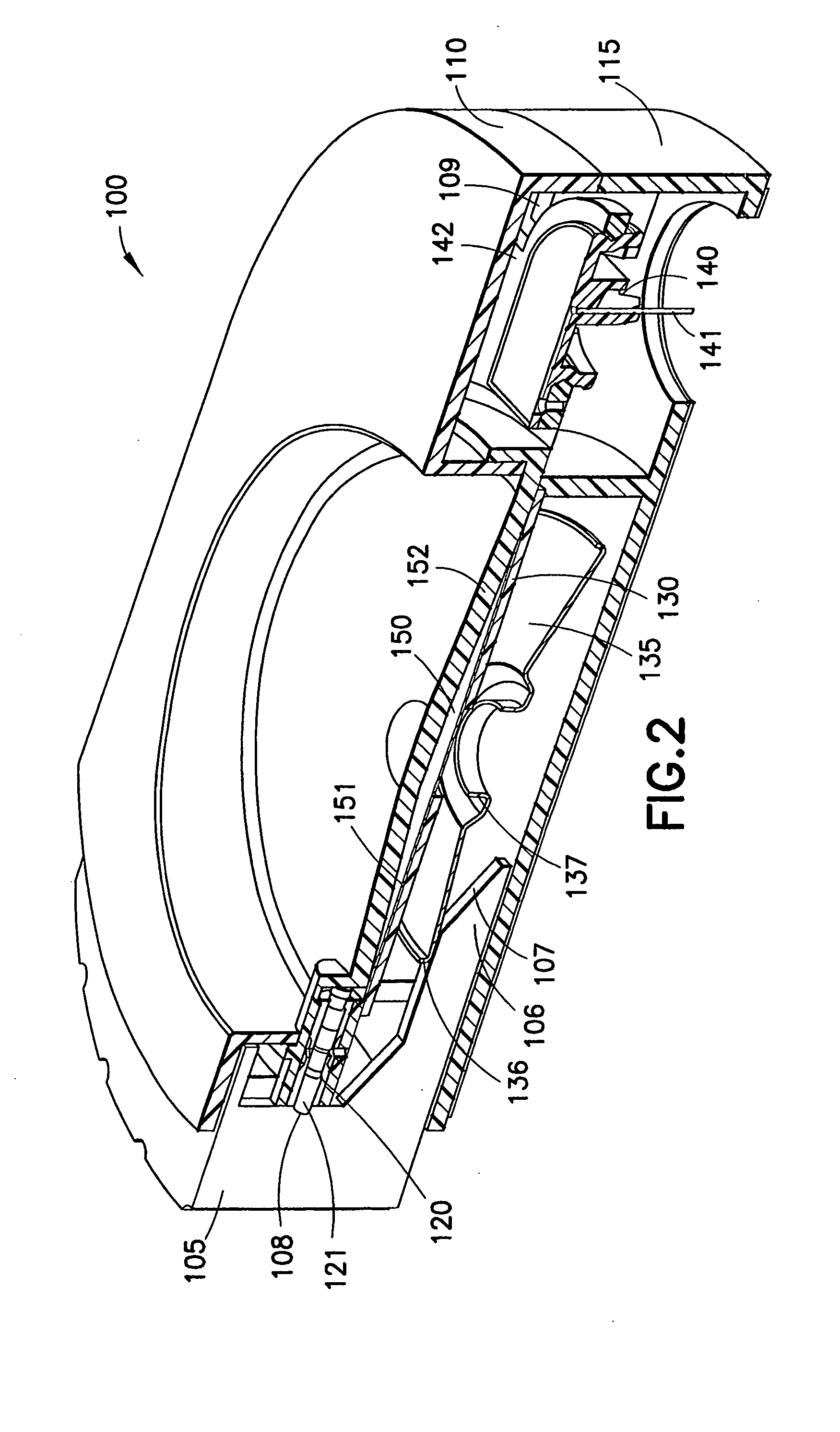
[0173] In a first embodiment of the device, shown in FIGS. 1 through 4, a push-button design 100 is shown wherein the activation and energizing of the device is accomplished in a single multi-function / step process. FIG. 1 is cross-sectional view of a first embodiment of a patch-like injector or infusor system using a side push button in an unactivated state, FIG. 2 is cross-sectional view of the embodiment shown in an activated state, FIG. 3 is cross-sectional view of the reservoir subassembly of the embodiment shown in FIG. 1, and FIG. 4 is cross-sectional view of the Belleville spring assembly of the embodiment shown in FIG. 1.
[0174] The device of FIGS. 1 through 4 includes a push button 105, an upper housing 110, a lower housing 115, a reservoir valve assembly 120, a Belleville spring 130, a spring retention disk 135, a manifold assembly 140, at least one patient needle 141 and a reservoir 150. The device can further include a needle shield 111, which protects the needles 141 an...
Example
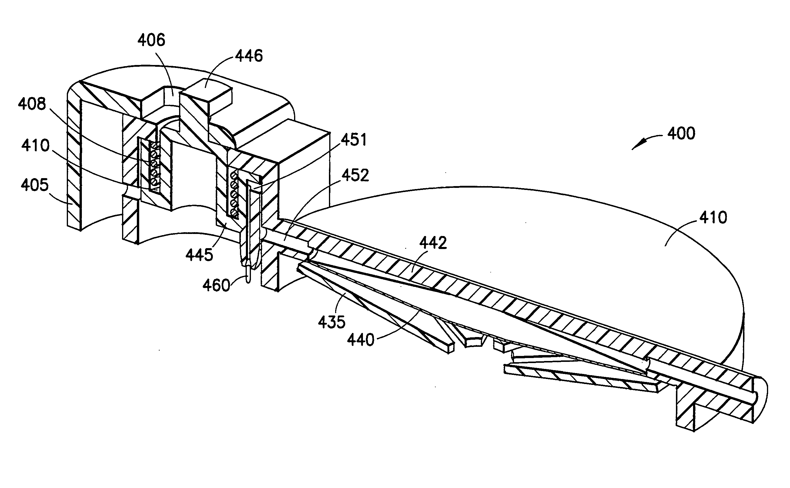
[0183] A second embodiment of a valve assembly 242 is shown in FIG. 7. FIG. 7 is cross-sectional view of a second valve assembly embodiment in an open position. The valve assembly 242 includes a plastic button 247, and is configured to operate as a pull valve. As shown in FIG. 7, when pushed forward, the plastic button 247 mateably engages a reservoir 150 opening and prevents fluid communication from the reservoir 150. When pulled from the reservoir 150 opening, the gap produced allows fluid communication along the conical face of the button 247 and to the fluid path 154 toward the patient needle manifold (not shown).
[0184] The valve assembly 242 has as an initial state and an activated state, and includes a large diameter distal end having a distal set of detents 243, a conical section 244 and a reduced diameter proximal end 245. In the initial state, the valve 242 distal detents 243 serve to prevent microbial ingress into the fluid path 246, and the conical section 244 and proxim...
Example
[0186] A third embodiment of a valve assembly 262 is shown in FIG. 8. FIG. 8 is cross-sectional view of a fourth valve assembly embodiment in an open position, and includes a plastic member 263, configured to operate as either a push or pull valve. As shown in FIG. 8, when pulled outward, the plastic member 263 obstructs a reservoir opening and prevents fluid communication from the reservoir 150. When pushed forward the plastic member aligns an opening and allows fluid communication between the reservoir 150 and the patient needle manifold 140 (not shown).
[0187] The valve assembly 262 has as an initial state and an activated state, and includes a distal end having a distal set of detents 264, and an enlarged diameter proximal end 265. In the initial state, the valve 262 distal detents 264 serve to prevent microbial ingress into the fluid path 267, and the enlarged proximal end 265 creates a seal with the end 266 of a plug insert member 270 to trap the drug safely within the reservo...
PUM
Abstract
A system and method for a patch-like, self-contained substance infusion device which provides one or more substantially hidden patient needles which can be placed in fluid communication with a fluid reservoir assembly that includes a rigid bladder portion used in conjunction with a non-distensible bladder film, such as a metallized film. The device can be attached to a skin surface via an adhesive contact surface and a push button activation assembly can then be used to remove an interlock, allowing a disk, or Belleville spring assembly to apply an essentially even and constant pressure to the contents of a fluid reservoir assembly. The push button activation assembly further allows the release of one or more spring-loaded patient needles into the skin surface, and establishes a fluid communication path between the patient needles and the pressurized fluid reservoir contents thereby delivering an infusion into the skin. The push button activation assembly further allows the release of one or more improved safety mechanisms after use.
Description
CROSS-REFERENCE TO RELATED APPLICATIONS [0001] This application claims the benefit under 35 U.S.C. §119(e) of a U.S. provisional patent application of Chris Cindrich et al. entitled “Patch-Like Infusion Device”, Ser. No. 60 / 494,286, filed on Aug. 12, 2003, and of a U.S. provisional patent application of Chris Cindrich et al. entitled “Patch-Like Infusion Device With Improved Valve, Spring And Safety Mechanisms”, Ser. No. 60 / 558,611, filed Apr. 2, 2004, the entire content of each of said applications being incorporated herein by reference. [0002] This application is a continuation-in-part of a U.S. nonprovisional patent application of Charles D. Shermer et al. entitled “Patch-Like Infusion Device”, Ser. No. 10 / 623,702, filed on Jul. 22, 2003, the entire content of which is incorporated herein by reference.FIELD OF THE INVENTION [0003] The present invention relates generally to a substance delivery device having improved valve, spring and safety mechanisms and to a patch-like, self-co...
Claims
Application Information
Patent Timeline
Application Date:The date an application was filed.
Publication Date:The date a patent or application was officially published.
First Publication Date:The earliest publication date of a patent with the same application number.
Issue Date:Publication date of the patent grant document.
PCT Entry Date:The Entry date of PCT National Phase.
Estimated Expiry Date:The statutory expiry date of a patent right according to the Patent Law, and it is the longest term of protection that the patent right can achieve without the termination of the patent right due to other reasons(Term extension factor has been taken into account ).
Invalid Date:Actual expiry date is based on effective date or publication date of legal transaction data of invalid patent.

