Braking system for a lift truck

a technology for braking systems and lift trucks, applied in the field of lift trucks, can solve problems such as inability to modulate brakes by pulsing the brake pedal, limited modulation may be available, and unstable conditions

Active Publication Date: 2010-03-23
CROWN EQUIP CORP
View PDF13 Cites 63 Cited by
  • Summary
  • Abstract
  • Description
  • Claims
  • Application Information

AI Technical Summary

Benefits of technology

[0007]In accordance with another aspect of the present invention, a method for operating a lift truck having first and second wheels located on first and second sides of the truck, respectively, a first brake associated with the first wheel, a second brake associated with the second wheel, an operator controlled service brake request device, a mast assembly along which forks are raised and lowered, and a mast height sensor comprises: applying a first braking force with the first brake to immobilize the truck; and applying a second braking force with the second brake to immobilize the truck, the first braking force being unequal to the second braking force.

Problems solved by technology

In these lift truck braking systems, limited modulation may be available by gradual application of the brake pedal and / or by pulsing the brake pedal to turn the brake on and off to thereby control the stopping distance.
Furthermore, in these braking systems, during a “fault” condition within the truck control system, even the ability to modulate the brakes by pulsing the brake pedal is not available since full braking torque is applied regardless of whether the brake pedal is operated or not.
Unfortunately, when a truck is operating with its forks elevated and particularly when the elevated forks support a load, full braking torque can result in an unstable condition.

Method used


Image

  • Braking system for a lift truck
  • Braking system for a lift truck
  • Braking system for a lift truck

Examples


Embodiment Construction

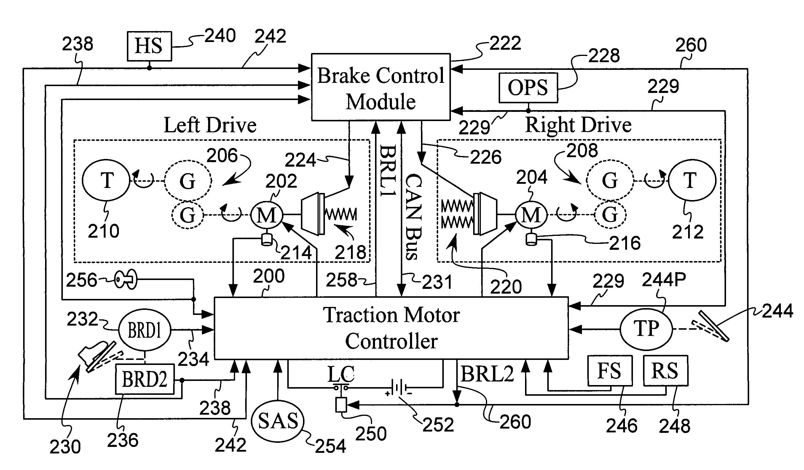
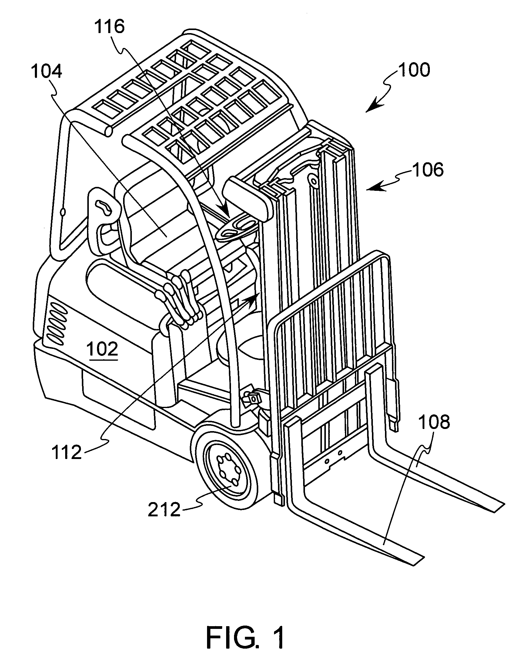
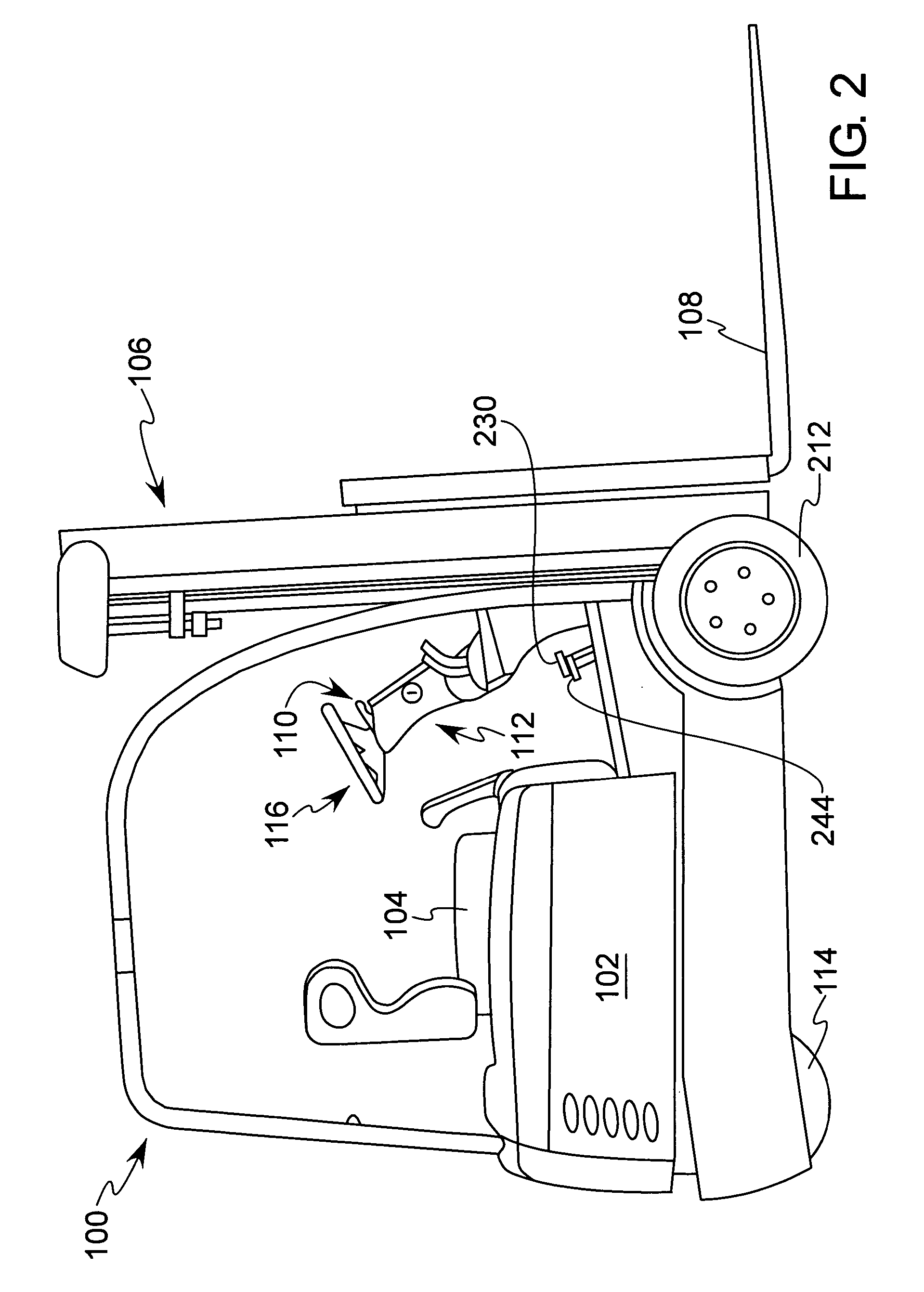
[0014]Reference is made to FIGS. 1 and 2 which are perspective and side plan views, respectively, of a three-wheel sit-down counterbalanced lift truck 100 for which the invention of the present application will initially be used. While the present invention is described herein with reference to the sit-down counterbalanced lift truck 100, it will be apparent to those skilled in the art that the invention and variations of the invention can be more generally applied to a variety of other materials handling vehicles including, without limitation, a three-wheel standup lift truck 100A shown in FIG. 5. Components that can be used to implement the invention of the present application on the lift trucks 100, 100A are illustrated schematically in FIG. 3 and also are identified in FIGS. 1, 2 and 5 to the extent these components are visible in FIGS. 1, 2 and 5. It is contemplated that other components and component configurations can be used for the present invention so that the invention is...


PUM


Abstract

A braking system for a lift truck performs all service braking using truck traction drive motors. Mechanical, spring applied, electrically released brakes are coupled to wheels on opposite sides of the truck with the mechanical brakes applying unequal braking forces to the wheels. The mechanical brakes perform park braking and, in the event an electrical system problem arises, backup braking as well that can be modulated by an operator of the truck regardless of the operating condition of the truck.

Description

[0001]This application claims the benefit of U.S. Provisional Patent Application No. 60 / 659,130 filed Mar. 7, 2005 and entitled BRAKING SYSTEM FOR A LIFT TRUCK which is incorporated herein by reference in its entirety.BACKGROUND OF THE INVENTION[0002]The present invention relates to lift trucks in general and, more particularly, to a braking system for a lift truck that permits simplified braking structure, elimination of replacement of brake wear components, improved operator comfort and improved lift truck stability during braking. While the present invention may be utilized on a variety of materials handling vehicles, it will be described herein with reference to a counterbalanced lift truck for which it is particularly applicable and will initially be used.[0003]Oftentimes, lift trucks, particularly standup lift trucks, utilize a “black and white” or on / off spring applied / electrically released brake arrangement to provide both service brakes (brakes for slowing or decelerating a...

Claims


Application Information

Patent Timeline
Patent Type & Authority Patents(United States)
IPC IPC(8): B60T8/62
CPCB60T13/04B60T13/662B66F9/07509B60T13/746B60T13/74B60T13/66B66F9/075F16D59/02
Inventor SHERMAN, DANIEL L.HAMMER, JOE K.
Owner CROWN EQUIP CORP
Why Eureka
Try Eureka