
Motorcycle front lighting apparatus structure

a technology for front lighting and motorcycles, applied in the direction of lighting and heating apparatus, bicycle equipment, optical signals, etc., can solve the problems of not being able to replace position lights with good ones individually, requiring a large amount of repair costs, and not being desirable from a design perspective, so as to improve indication performance and appearance, easy to make large, and the effect of simple mounting structur

Active Publication Date: 2010-04-13
HONDA MOTOR CO LTD
View PDF11 Cites 2 Cited by
  • Summary
  • Abstract
  • Description
  • Claims
  • Application Information

AI Technical Summary

Benefits of technology

The present invention provides a front lighting apparatus structure for a motorcycle that allows for easy adjustment of the position light to improve indication performance and appearance. The position light can be mounted on the headlight or separately, making it easier to repair and reducing the cost of repair. The structure also allows for compact assembly of the headlight and position light, and simplifies the mounting structure by eliminating a heavy-weight part. The technical effects of the invention include improved appearance, improved indication performance, and cost-effective repair.

Problems solved by technology

This is not desirable from a design viewpoint.
If the headlight fogs or a related problem occurs as a result of water entry in the case because of a defective position light, the position light cannot be replaced with a good one individually.
This makes it necessary to replace the entire headlight, requiring a large amount of repair cost.

Method used


Image

  • Motorcycle front lighting apparatus structure
  • Motorcycle front lighting apparatus structure
  • Motorcycle front lighting apparatus structure

Examples


first embodiment

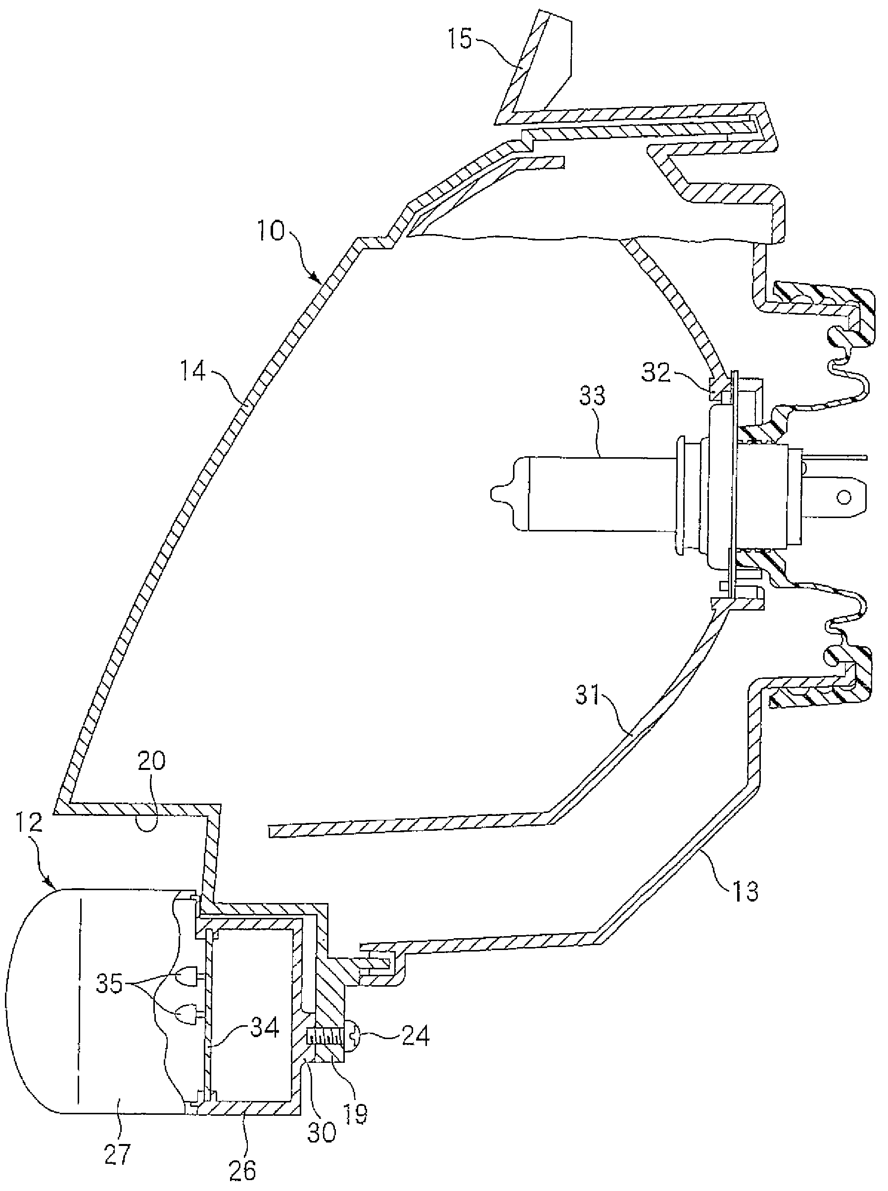
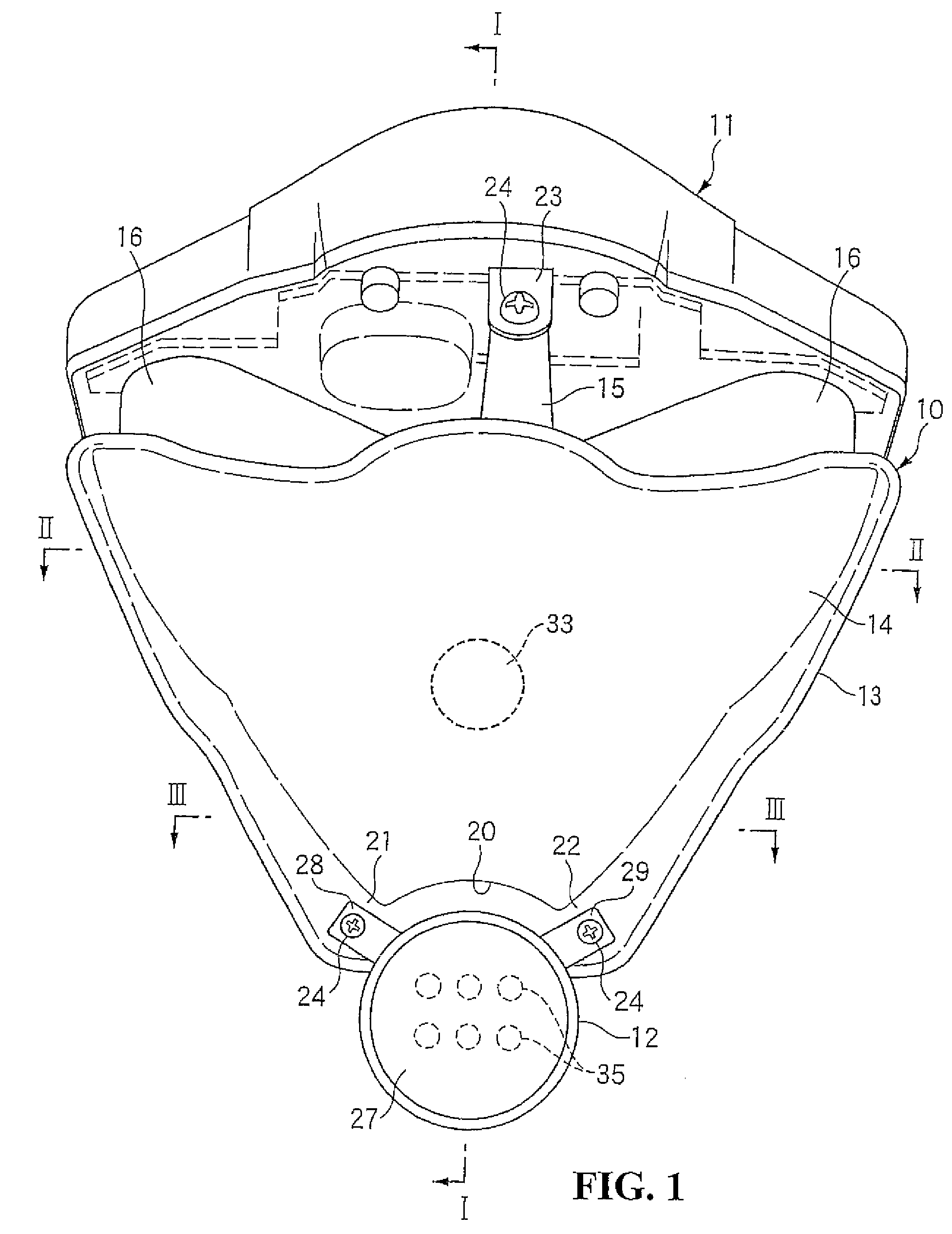
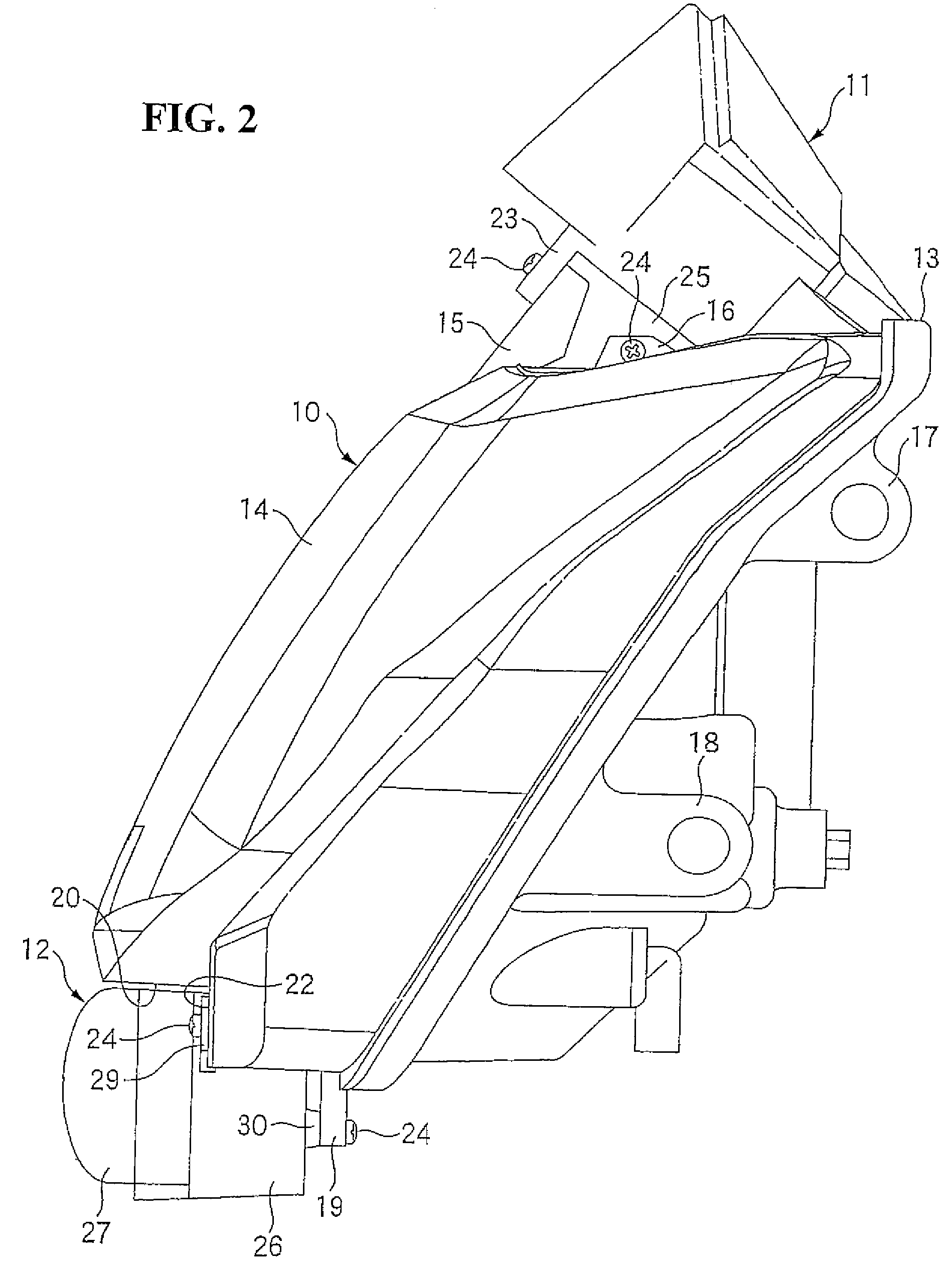
[0038]Referring to FIGS. 1 and 2, the motorcycle front lighting apparatus structure according to the present invention includes a headlight unit 10, a meter unit 11, and a position light 12.

[0039]The headlight unit 10 includes a headlight case 13 formed into a substantially V shape and a transparent headlight lens 14 fitted to a front portion of the headlight case 13.

[0040]The headlight case 13 includes a center bracket 15 and a pair of side brackets 16. The center bracket 15 is formed at a center and the side brackets 16 are formed on sides at an upper portion of the headlight case 13. The center bracket 15 and the side brackets 16 are formed in an upwardly protruding condition.

[0041]The headlight case 13 further includes a pair of upper brackets 17 and a pair of lower brackets 18. The upper brackets 17 and the lower brackets 18 are formed on the sides of the headlight case 13. In addition, the headlight case 13 includes a rear side position light bracket 19 formed on a lower end o...

second embodiment

[0061]FIGS. 6 through 17 are views showing the present invention.

[0062]Referring to FIGS. 6 through 8, the front lighting apparatus structure for a motorcycle according to the second embodiment of the present invention includes a headlight unit 50, a position light 90, a turn signal light 110, a meter unit 120, and a headlight stay 140 for mounting the foregoing parts at the front side of the motorcycle.

[0063]The headlight unit 50 includes a headlight case 51, a headlight lens 52, a pair of headlight side covers 53, 54, and a headlight lower cover 55. More specifically, the headlight lens 52 is a transparent part disposed at a front portion of the headlight case 51, having a substantially V-shaped front view. The pair of headlight side covers 53, 54 covers an upper portion and sides of the headlight lens 52. The headlight lower cover 55 covers an area surrounding the position light 90 disposed at a lower portion of the headlight lens 52 and extends obliquely upwardly alongside the h...


PUM


Abstract

A motorcycle front lighting apparatus structure includes a headlight and a position light provided adjacent to the headlight. In this structure, the position light is disposed in a condition protruding downwardly from a lower edge of the headlight. This structure allows the position light to be made larger, and makes any needed repair easy and cost effective.

Description

CROSS-REFERENCE TO RELATED APPLICATION[0001]The present application claims priority under 35 U.S.C. §119 to Japanese Patent Application No. 2007-095425, filed Mar. 30, 2007, and Japanese Patent Application No. 2007-272693, filed Oct. 19, 2007, the entire contents of which are hereby incorporated by reference.BACKGROUND OF THE INVENTION[0002]1. Field of the Invention[0003]The present invention relates to a front lighting apparatus structure for a motorcycle, including a headlight and a position light provided according to the headlight.[0004]2. Description of Background Art[0005]A known motorcycle front lighting apparatus structure includes a position light integrated into a case for a headlight (see, for example, Japanese Patent Laid-open No. 2000-57807).[0006]A headlight mounting structure is known, in which a meter unit is mounted on a headlight, the headlight is attached to housing by tightening, and the housing is rotatably supported on a stay of the headlight (see, for example,...

Claims


Application Information

Patent Timeline
Patent Type & Authority Patents(United States)
IPC IPC(8): F21V33/00
CPCB60Q1/0047B62J6/02B60Q1/0433B62J6/026
Inventor OTA, HIROYASUASHIHARA, EIJI
Owner HONDA MOTOR CO LTD
Learn More