Frequency jittering control for varying the switching frequency of a power supply

a power supply and frequency jittering technology, applied in the field of switching mode power supply, can solve the problems of inducing loud electromagnetic interference (emi), disadvantageous to chip circuit integration, and cost reduction

Active Publication Date: 2010-04-20
RICHTEK TECH
View PDF10 Cites 60 Cited by
  • Summary
  • Abstract
  • Description
  • Claims
  • Application Information

AI Technical Summary

Problems solved by technology

Unfortunately, a strong noise would be generated at such switching frequency and its relative harmonic, thereby inducing loud electromagnetic interference (EMI).
However, this art requires a huge capacitor to be charged and discharged, which is disadvantageous to cost reduction and chip circuit integration.

Method used


Image

  • Frequency jittering control for varying the switching frequency of a power supply
  • Frequency jittering control for varying the switching frequency of a power supply
  • Frequency jittering control for varying the switching frequency of a power supply

Examples


Embodiment Construction

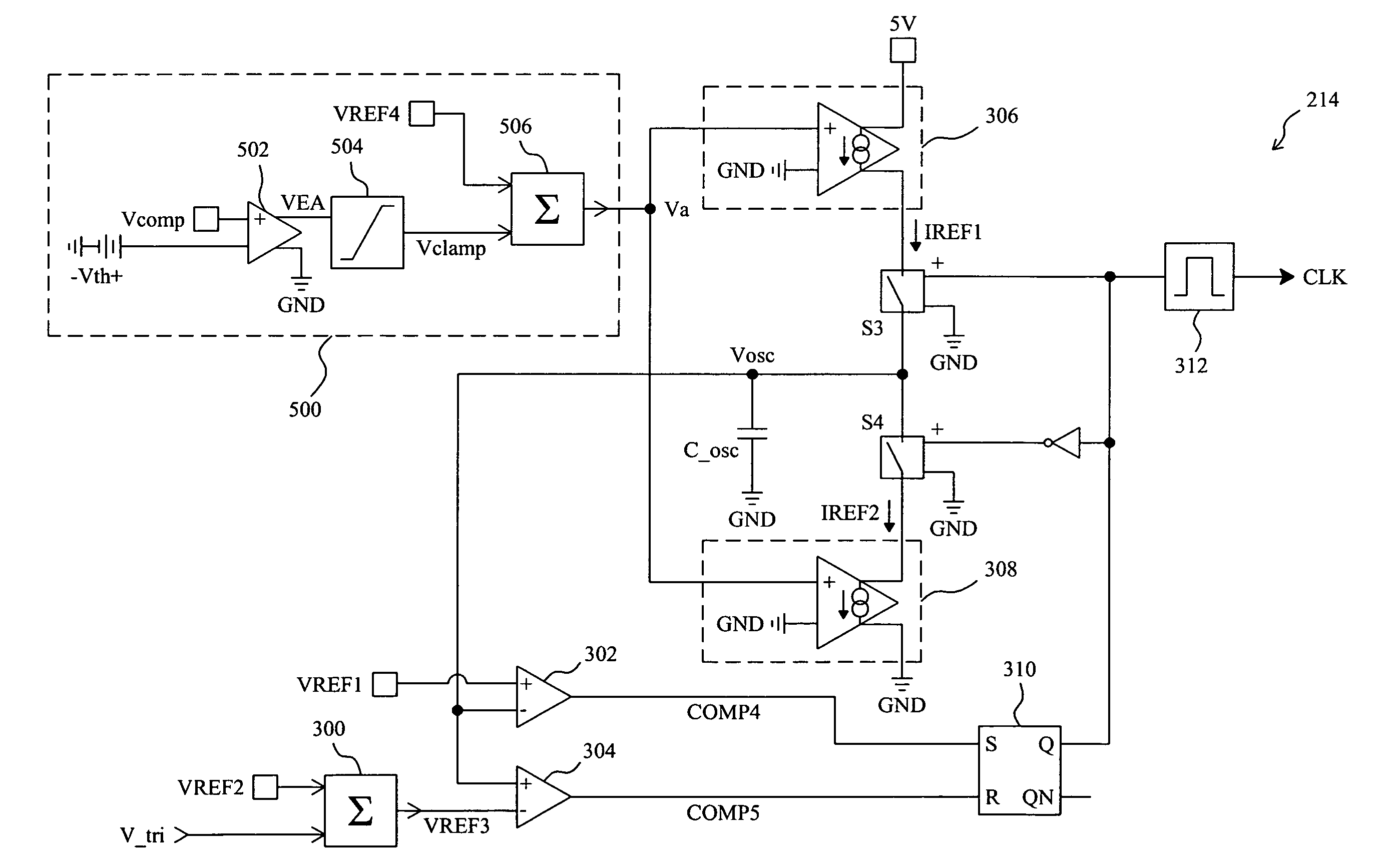
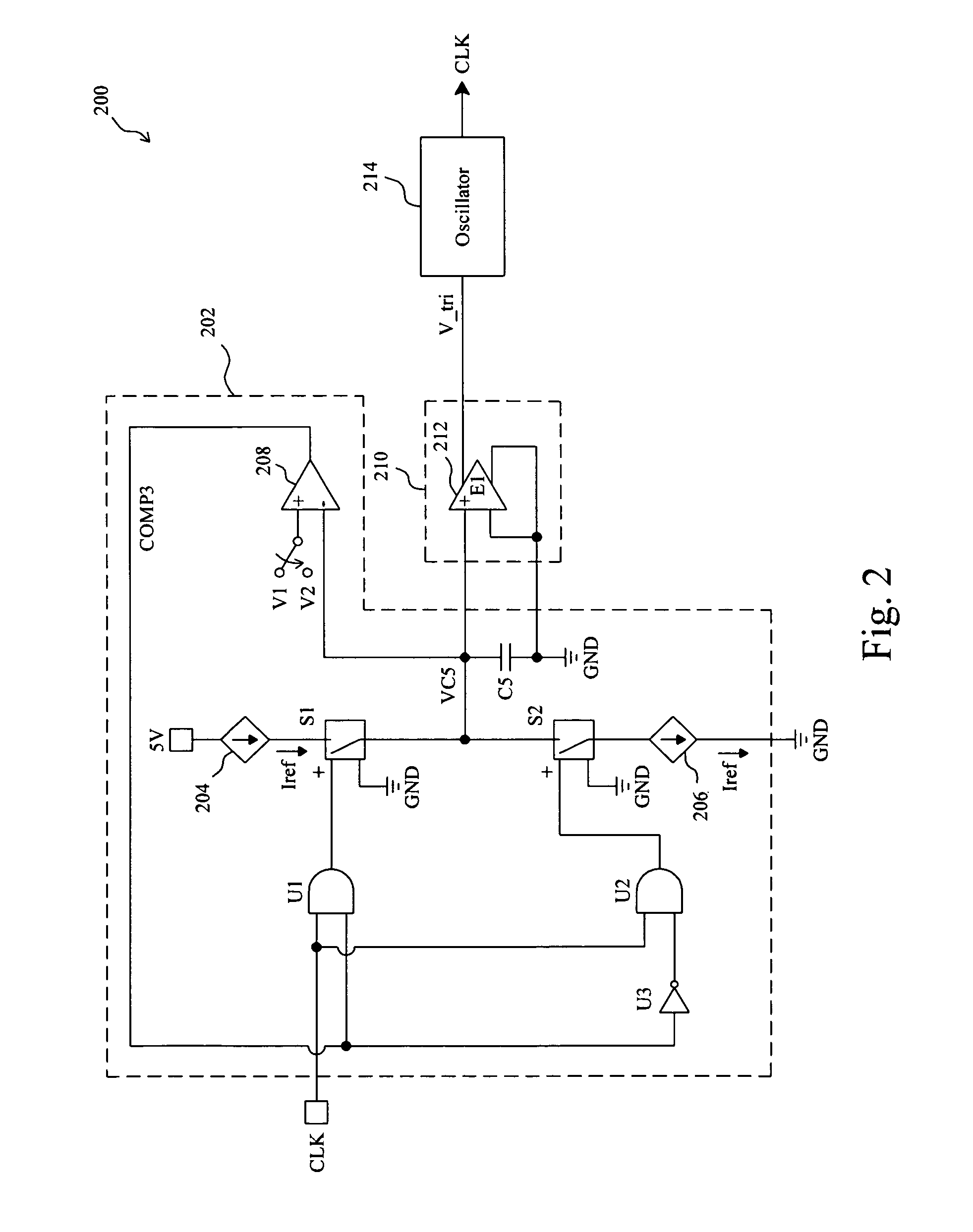
[0013]As an embodiment according to the present invention shown in FIG. 2, a frequency jittering circuit 200 has a hysteretic band modulator 202 to modulate the hysteretic band for generating a clock for a switching mode power supply. The hysteretic band modulator 202 generates a low-frequency signal VC5 under clocking of a clock CLK, and a gain circuit 210 includes an amplifier 212 of gain E1 to amplify the low-frequency signal VC5 to thereby generate a modifying signal V_tri for an oscillator 214. The modifying signal V_tri modifies the hysteretic band of the oscillator 214, and thus the hysteretic band varies with time. In the hysteretic band modulator 202, a current source 204 is connected to a capacitor C5 via a switch S1, a current source 206 is connected to the capacitor C5 via a switch S2, and a voltage comparator 208 detects the low-frequency signal VC5 to generate a comparison signal COMP3. The comparison signal COMP3 and the clock CLK are used to switch the switches S1 an...


PUM


Abstract

A frequency jittering circuit modulates a hysteretic band of an oscillator such that the clock generated by the oscillator has a jitter frequency, and thus a switching mode power supply operative on the clock will have a jittering switching frequency.

Description

FIELD OF THE INVENTION[0001]The present invention generally relates to a switching mode power supply and, more particularly, to a frequency jittering circuit and method for varying the switching frequency of a power supply.BACKGROUND OF THE INVENTION[0002]Most switching mode power supplies operate at a fixed and fast switching frequency. Unfortunately, a strong noise would be generated at such switching frequency and its relative harmonic, thereby inducing loud electromagnetic interference (EMI). Jittering or dithering switching frequency can distribute the noise's energy to a broad band, and thus depresses the noise and improves the performance in conduction of EMI. As is well known in the art, the switching frequency of a switching mode power supply depends on the clock frequency of the oscillator in the power supply. For further detail, FIG. 1 shows a conventional oscillator 100, in which a comparator 102 will trigger a comparison signal COMP1 to a set input S of a flip-flop 110 ...

Claims


Application Information

Patent Timeline
Patent Type & Authority Patents(United States)
IPC IPC(8): H03K3/02H03K7/00
CPCH04B15/005H03K7/06H03K3/84H02M1/44H02M3/156
Inventor LIN, TZU-CHENHUANG, PEI-LUNCHOU, HUNG-CHE
Owner RICHTEK TECH
Why Eureka
Try Eureka