Process of molding a coupling for interconnecting tubes

Active Publication Date: 2010-05-04
SAINT GOBAIN PERFORMANCE PLASTICS CORP +1
View PDF21 Cites 53 Cited by
  • Summary
  • Abstract
  • Description
  • Claims
  • Application Information

AI Technical Summary

Benefits of technology

[0031]A specific embodiment of the present invention is shown in the attached drawings. For the purpose of summarizing the invention, the invention relates to an improved apparatus and a process of molding a coupling for interconnecting a primary and a secondary tube, comprising the steps of inserting a primary core pin into an end of the primary tube. A secondary core pin is inserted into an end of the second tube to abut with the primary core pin. The assemb

Problems solved by technology

Upon opening of the mold, the core in many instances would interfere with the removal of the reproduction from the mold cavity.
Although the art of molding object has progressed substantially from primitive times, process of removing the core from a mold cavity after formation of the reproduction is still a problem in the molding art.
In some instances, it is impossible to withdraw a core pin from a mold cavity prior to opening the mold.
In these instances, the problem of removing the reproduction from the mold cavity after the molding process is still a problem in the molding art.

Method used


Image

  • Process of molding a coupling for interconnecting tubes
  • Process of molding a coupling for interconnecting tubes
  • Process of molding a coupling for interconnecting tubes

Examples


first embodiment

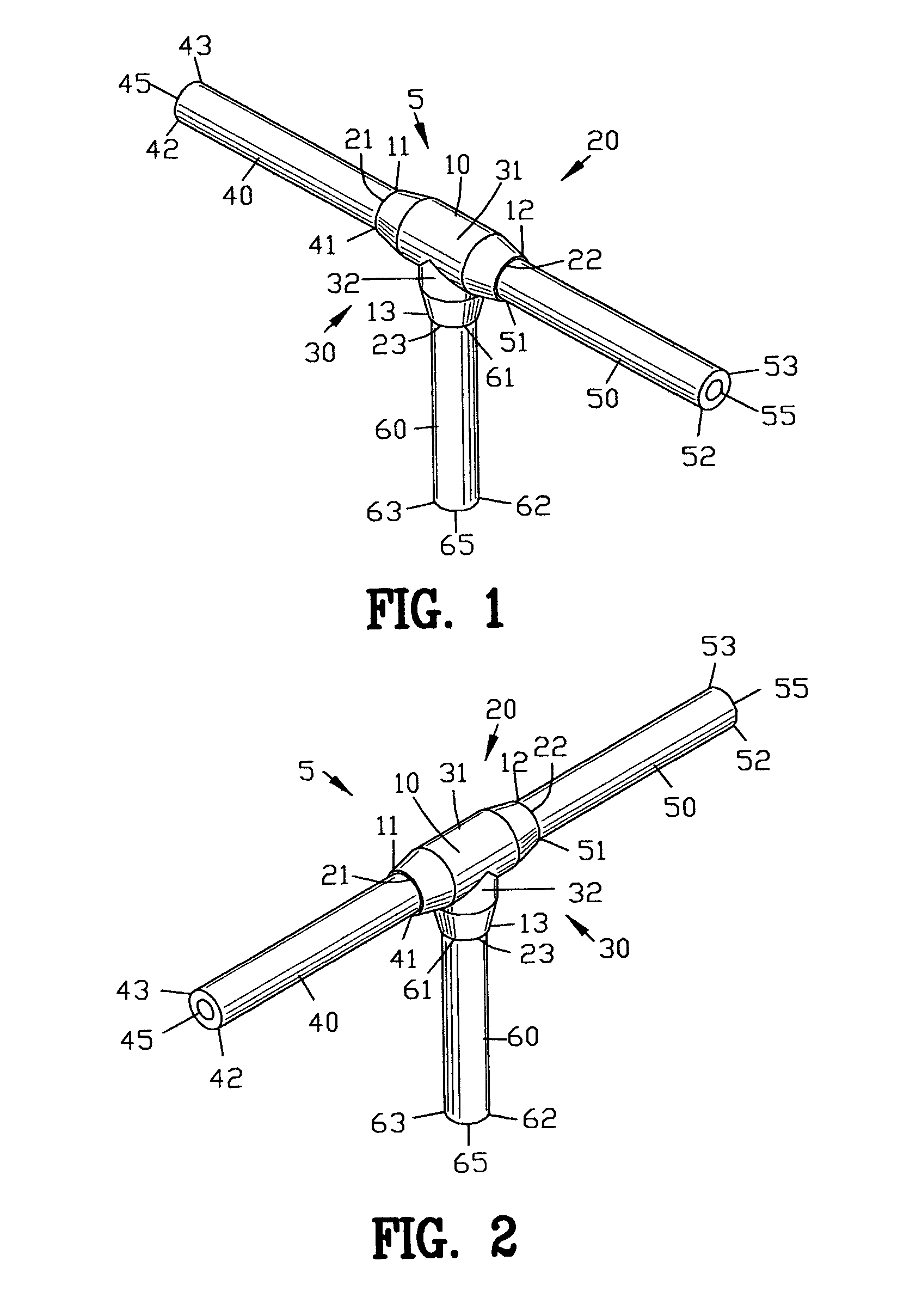
[0062]FIGS. 1 and 2 are front and rear isometric views of a coupling 5 of the present invention. The coupling 5 comprises a body member 10 having a first end 11, a second end 12, and a third end 13. The coupling 5 comprises a plurality of apertures 20 shown as a first aperture 21, a second aperture 22, and a third aperture 23.

[0063]A plurality of bores 30 comprising a first or primary bore 31 and a second or secondary bore 32 are defined within the coupling 5. The first and second apertures 21 and 22 are interconnected by the primary bore 31. The secondary bore 32 is interconnected to the primary bore 31.

[0064]A plurality of tubes shown as a first tube 40, a second tube 50 and a third tube 60 are connected to the coupling 5. The first tube 40 comprises a first end 41 and a second end 42. The first tube 40 is defined by an outer surface 43 and an inner bore 45. Preferably, the first tube 40 is formed from a flexible polymeric material. In one example, the first tube 40 is formed with...

second embodiment

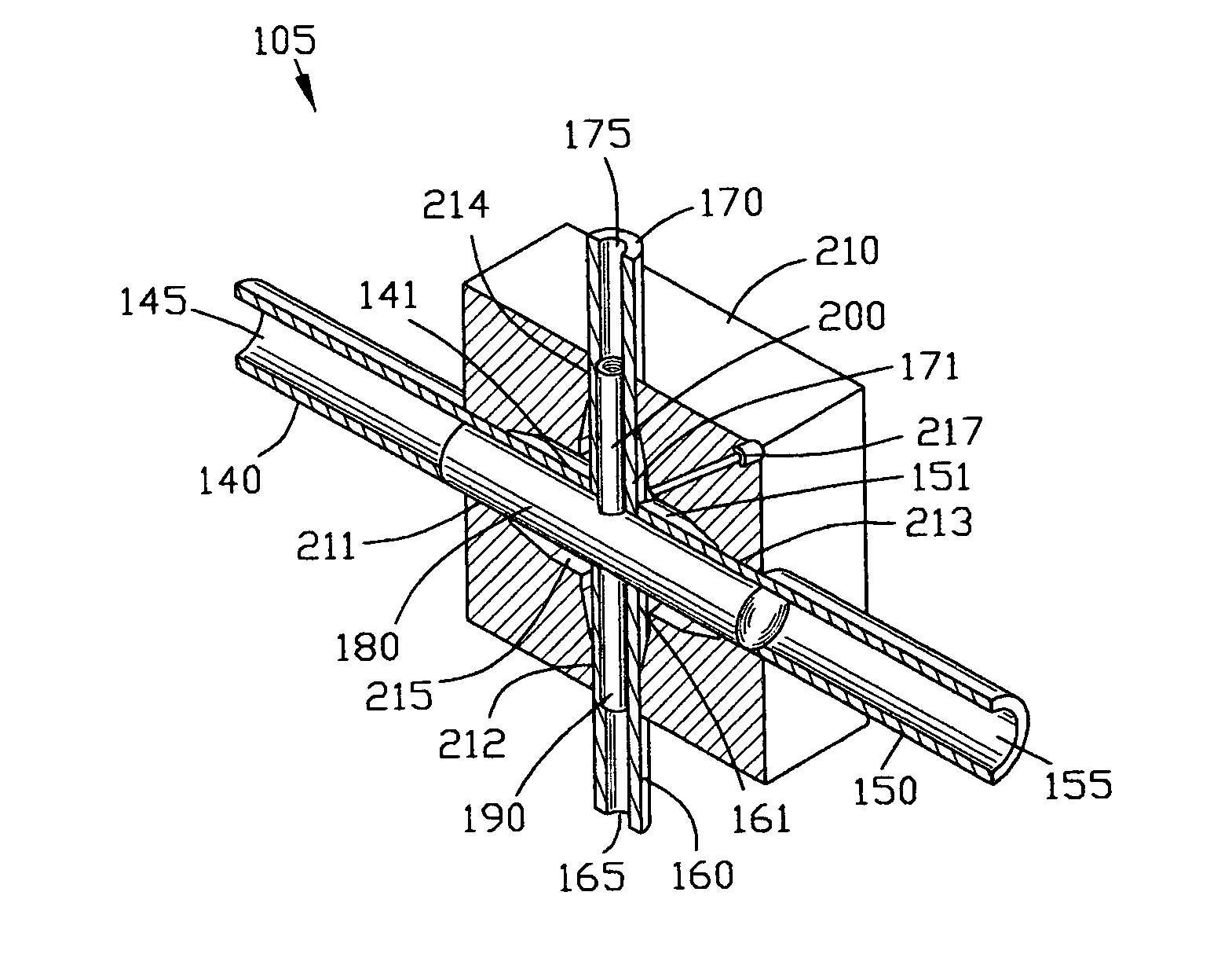
[0081]FIGS. 10 and 11 are front and rear isometric views of a coupling 105 of the present invention. The coupling 105 comprises a body member 110 having a first end 111, a second end 112, a third end 113, and a fourth end 114. The coupling 105 comprises a plurality of apertures 120 shown as a first aperture 121, a second aperture 122, a third aperture 123 and a fourth aperture 124.

[0082]A plurality of bores 130 comprising a first or primary bore 131 and a second or secondary bore 132 are defined within the coupling 105. The first and second apertures 121 and 122 are interconnected by the primary bore 131. The third and fourth apertures 123 and 124 are interconnected by the secondary bore 132 through the primary bore 131.

[0083]A plurality of tubes shown as a first tube 140, a second tube 150, a third tube 160 and a fourth tube 170 are connected to the coupling 105. The first tube 140 comprises a first end 141 and a second end 142. The first tube 140 is defined by an outer surface 143...


PUM

PropertyMeasurementUnit
Thicknessaaaaaaaaaa
Pressureaaaaaaaaaa
Angleaaaaaaaaaa

Abstract

A coupling and a process of molding the coupling is disclosed for interconnecting a primary and a secondary tube. The process comprises the steps of inserting a primary core pin into the primary tube. A secondary core pin is inserted into the second tube to abut with the primary core pin. The assembled tubes and core pins are placed within a mold cavity and a thermoplastic material is injected for forming the coupling. The coupling and the interconnected tubes are removed from the mold cavity. The secondary core pin is disengaged from the secondary core pin to be removed by passing the secondary core pin through the secondary tube. The primary core pin is removed by passing the secondary core pin through the primary tube. The coupling forms a smooth interconnection of the inner cross-sections of the first and second tubes.

Description

CROSS-REFERENCE TO RELATED APPLICATIONS[0001]This application claims benefit of U.S. Patent Provisional application Ser. No. 60 / 546,584 filed Feb. 19, 2004, now abandoned. All subject matter set forth in provisional application Ser. No. 60 / 546,584 is hereby incorporated by reference into the present application as if fully set forth herein.BACKGROUND OF THE INVENTION[0002]1. Field of the Invention[0003]This invention relates to couplings and more particularly to a new and improved coupling for interconnecting plural tubes and a method of forming the coupling.[0004]2. Background of the Invention[0005]Apparatuses and processes have been well known in the art throughout history for moldings a new object. In primitive molding processes, a mold cavity was formed within a mold to form a new object. The mold cavity was cut into the mold in the shape of the new object. A liquefied material was poured into a mold cavity to solidify within the mold cavity. After the solidification of the liqu...

Claims


Application Information

Patent Timeline
IPC IPC(8): B29C45/14
CPCB29C45/14598B29C33/76
Inventor HELICKE, ALBERT H.SMITH, DENNIS M.
Owner SAINT GOBAIN PERFORMANCE PLASTICS CORP
Why Eureka
Try Eureka