
Surgical instruments employing sensors

a technology of surgical instruments and sensors, applied in the field of surgical instruments, can solve the problems of limited control, conventional surgical instruments cannot mesurably detect the amount of tissue positioned between tissue contacting surfaces of end effectors, and surgical instruments used in open and minimally invasive surgery are limited in their ability to sense and/or control

Active Publication Date: 2010-05-18
TYCO HEALTHCARE GRP LP
View PDF42 Cites 1854 Cited by
  • Summary
  • Abstract
  • Description
  • Claims
  • Application Information

AI Technical Summary

Benefits of technology

The present disclosure provides a surgical instrument for operating on tissue that includes an end effector with two tissue engaging members in juxtaposed relation to each other. The instrument also includes a gap determination element and a tissue contact determining element for measuring the gap between the two tissue engaging members and the contact between the instrument and the tissue. The instrument can be a stapler and the method includes approximating the tissue engaging members until the tissue is compressed, monitoring the compression force and strain on the tissue, and stopping the approximation when the predetermined level of compression or strain is reached. The technical effect of this patent is to provide a surgical instrument with improved accuracy in measuring the gap between the two tissue engaging members and the contact between the instrument and the tissue, which can enhance the precision of the surgical procedure.

Problems solved by technology

Surgical instruments used in open and minimally invasive surgery are limited in their ability to sense and / or control conditions and / or parameters and factors critical to effective operation.
For example, conventional surgical instruments cannot measurably detect the amount of tissue positioned between tissue contacting surfaces of an end effector of the surgical instrument, the clamping force being exerted on the tissue, the distance between juxtaposed tissue contacting surfaces, and / or the viability of the tissue clamped therebetween.

Method used


Image

  • Surgical instruments employing sensors
  • Surgical instruments employing sensors
  • Surgical instruments employing sensors

Examples


Embodiment Construction

[0049]Preferred embodiments of the presently disclosed surgical instruments and systems will now be described in detail with reference to the drawing FIGS. wherein like reference numerals identify similar or identical elements. As used herein and as is traditional, the term “distal” will refer to that portion which is further from the user while the term “proximal” will refer to that portion which is closer to the user.

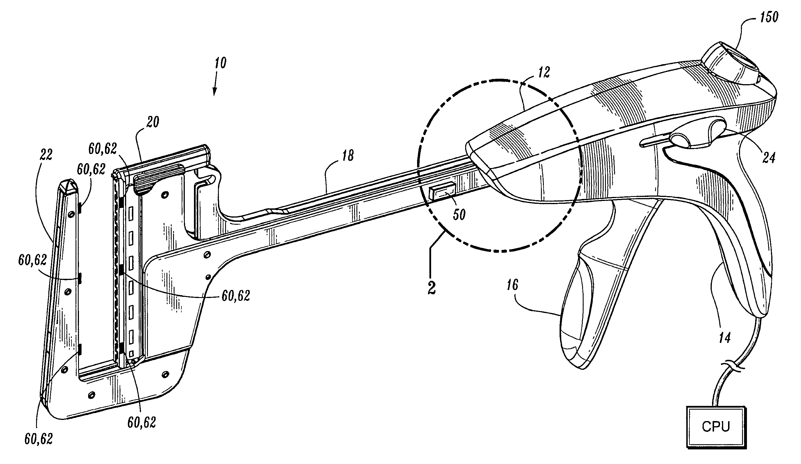
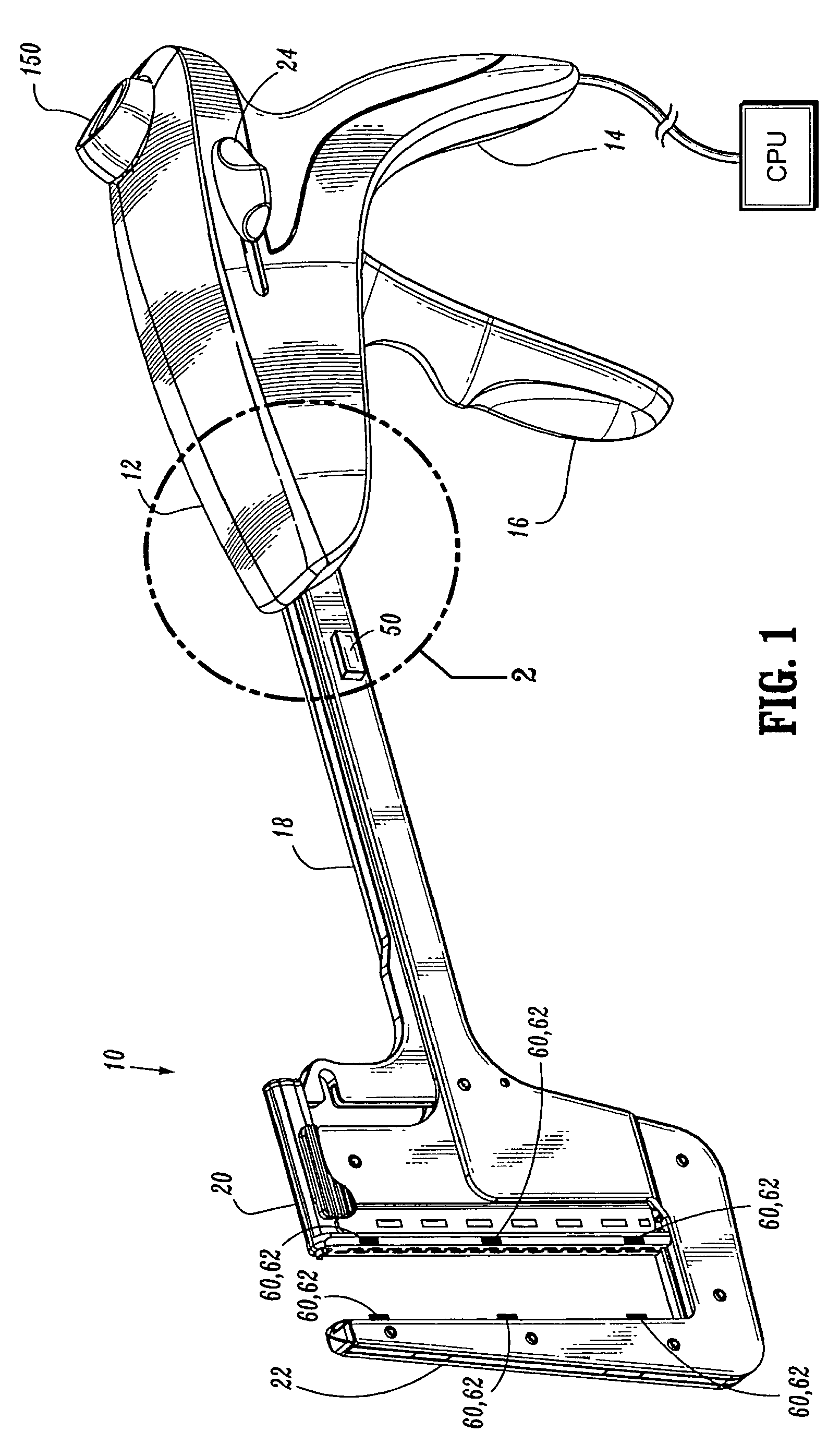
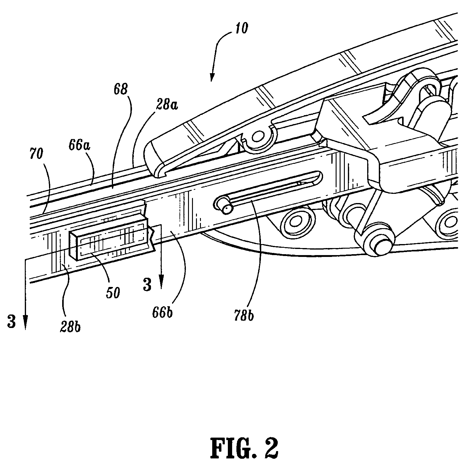
[0050]A surgical instrument in accordance with an embodiment of the present disclosure is shown generally as 10 in FIGS. 1-6A. Surgical instrument 10 includes a body 12 defining a stationary handle 14, a pivotable trigger 16, an elongated central body portion 18, and an end effector including a first member or cartridge assembly 20 and a second member of anvil assembly 22. A thumb button 24 is slidably positioned on each side of body 12. Thumb buttons 24 are movable to manually advance an alignment pin assembly (not shown). A release button 150 is positioned on the pr...


PUM

PropertyMeasurementUnit
lengthaaaaaaaaaa
lengthsaaaaaaaaaa
gap distanceaaaaaaaaaa

Abstract

According to an aspect of the present disclosure, a surgical instrument for operating on tissue is provided. The surgical instrument includes an end effector including a first tissue engaging member and a second tissue engaging member in juxtaposed relation to the first tissue engaging member; a gap determination element operatively associated with each of the first tissue engaging member and the second tissue engaging member for measuring a gap distance between the first tissue engaging member and the second tissue engaging member; and a tissue contact determining element operatively associated with a respective tissue contacting surface of at least one of the first tissue engaging member and the second tissue engaging member. The present disclosure also relates to methods of using the surgical instrument.

Description

CROSS-REFERENCE TO RELATED APPLICATIONS[0001]The present application claims the benefit of and priority to U.S. Provisional Application No. 60 / 687,243, filed Jun. 3, 2005, and U.S. Provisional Patent Application Ser. No. 60 / 687,214, filed on Jun. 3, 2005, the entire contents of each of which being incorporated herein by reference.BACKGROUND[0002]1. Technical Field[0003]The present disclosure relates to surgical instruments and, more particularly, to mechanical, electromechanical and energy-based surgical instruments and systems.[0004]2. Background of Related Art[0005]Surgical instruments used in open and minimally invasive surgery are limited in their ability to sense and / or control conditions and / or parameters and factors critical to effective operation. For example, conventional surgical instruments cannot measurably detect the amount of tissue positioned between tissue contacting surfaces of an end effector of the surgical instrument, the clamping force being exerted on the tissu...

Claims


Application Information

Patent Timeline
Patent Type & Authority Patents(United States)
IPC IPC(8): A61B17/068
CPCA61B17/068A61B17/072A61B17/07207A61B17/115A61B17/128A61B17/0686A61B2019/4857A61B17/29A61B2017/00022A61B2017/00039A61B2017/00106A61B2017/00119A61B2017/07214A61B2019/461A61B2019/465A61B2090/061A61B2090/065A61B2090/0811A61B90/06A61B17/1155A61B34/10
Inventor BEETEL, ROBERT J.
Owner TYCO HEALTHCARE GRP LP
Learn More