Acoustic vibratory plate

a vibratory plate and acoustic technology, applied in the direction of transducer diaphragms, electromechanical transducers, instruments, etc., can solve the problems of high internal loss, high damping property, and critical issue of split vibration band peak-dip flattening, etc., to increase internal loss, increase damping property, and improve the effect of internal loss

Inactive Publication Date: 2010-06-01
SONY CORP
View PDF29 Cites 36 Cited by
  • Summary
  • Abstract
  • Description
  • Claims
  • Application Information

AI Technical Summary

Benefits of technology

[0016]It is desirable to provide an acoustic vibratory plate that effectively increases an internal loss and realizes the flattening of peak-dip of a split vibration band.
[0019]The acoustic vibratory plate according to the embodiments of the present invention effectively increases the internal loss and realizes an increase in damping property, thereby realizing the flattening of peak-dip of a split region.

Problems solved by technology

Furthermore, for flattening, a high internal loss, that is, high damping property is required.
However, in the reproduction at 100 kHz in recent years, it is very difficult to perform the reproduction at 100 kHz with only the piston band B1 and thus, a reproduction technique of using the split vibration band B2 is required, which makes the flattening of peak-dip of the split vibration band B2 critical issue.
In the past, although a method of applying a damping agent has been used in order to flatten the peak-dip, this method of applying the damping agent has only moderately beneficial and does not bring about a sufficient damping property.

Method used


Image

  • Acoustic vibratory plate
  • Acoustic vibratory plate
  • Acoustic vibratory plate

Examples


example 1

[0052]Using a biaxially stretched polyester film (hereinafter, referred to as “PET film”) as the polymer material A and a polyester-based adhesive for laminate composed of a polyester resin (hereinafter, referred to as “LA”) as the polymer material B which is the damping agent, the properties of the polymer materials A, B were measured, and using the measured values, simulation based on a visco-elastic theory was conducted to compare Comparative Example 1 to which a related art method is applied and Example 1 to which the present invention is applied.

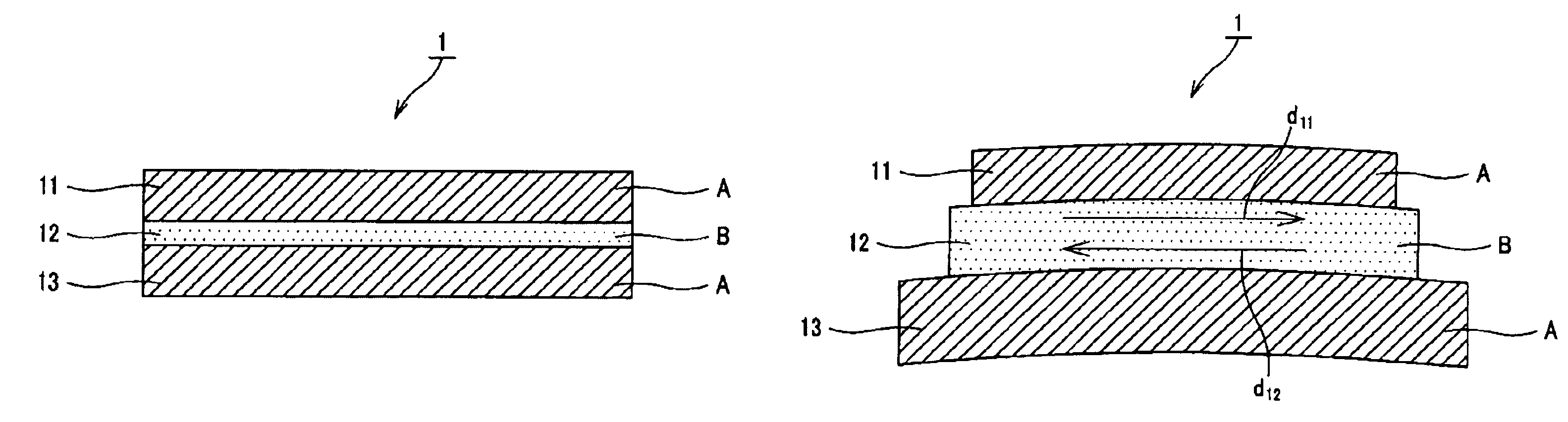
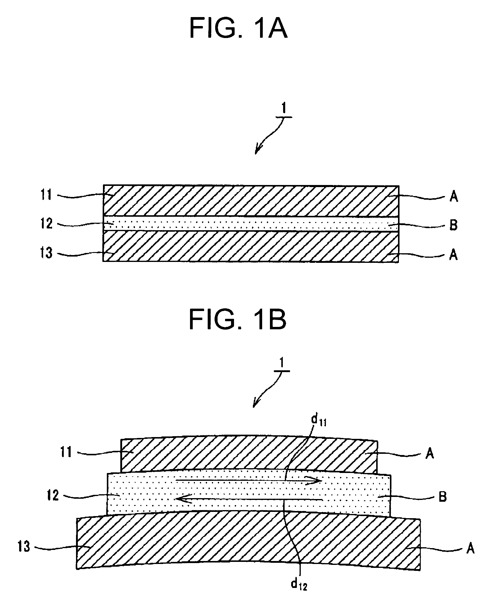
[0053]In the comparative simulation, as Example 1 to which the present invention is applied, a three-layered structure in which the laminated bodies were layered in the order of A / B / A, that is, constitution similar to the one shown in FIG. 1A was employed. PET films were used as the polymer material A forming the first and third laminated bodies 11, 13 and were formed with a thickness of 3 microns, respectively, and an LA was used as th...

example 2

[0068]In Example 2, a three-layered structure in which the laminated bodies were layered in the order of A / B / A, that is, constitution similar to the constitution as shown in FIG. 1A was employed. PET films were used as the polymer material A forming the first and third laminated bodies 11, 13 and were formed with a thickness of 25 microns, respectively, and an LA was used as the damping agent B forming the second laminated body 12, and was formed with a thickness of 10 microns to form a complex (of three-layered structure) making up an acoustic vibratory plate. For the complex of Example 2 formed in such a manner, an internal loss was obtained by a vibration reed method.

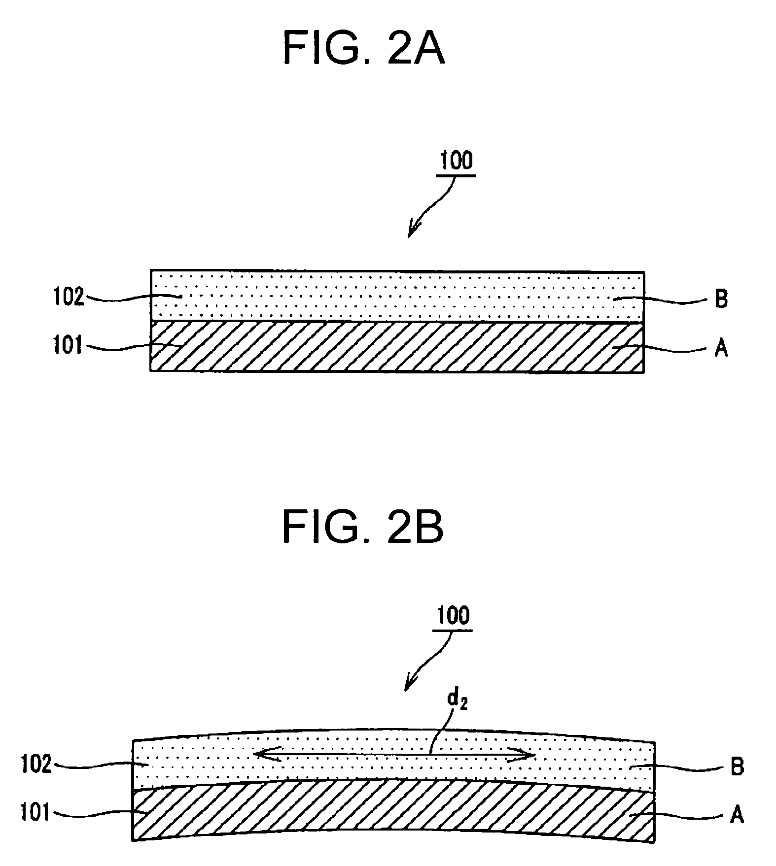
[0069]As Comparative Example 2, a two-layered structure in which the laminated bodies were layered in the order of A / B, that is, constitution similar to the constitution shown in FIG. 2A was employed. As the polymer material A forming the first laminated body 101, a PET film was used similar to the polymer material A...

example 3

[0073]In Example 3, a Balance Dome Tweeter (hereinafter, referred to as “Tw”) with a diameter of 25 mm was manufactured using the complex having the three-layered structure constituted in Example 2, and its reproduction frequency response was measured.

[0074]Furthermore, in order to compare with Example 3, as Comparative Example 3-1, a Balance Dome Tw with a diameter of 25 mm was manufactured similar to Example 3, using the complex having the two-layered structure constituted in the above-described Comparative Example 2. Furthermore, as Comparative Example 3-2, a Balance Dome Tw with a diameter of 25 mm was manufactured similar to Example 3, using a PET film alone of 50 microns.

[0075]FIG. 3 shows the results obtained by measuring reproduction frequency responses of the Tw's using the complexes of Example 3, and Comparative Examples 3-1, 3-2. In FIG. 3, L3 indicates the reproduction frequency response of Example 3, L31 indicates the reproduction frequency response of Comparative Examp...


PUM

PropertyMeasurementUnit
frequencyaaaaaaaaaa
frequencyaaaaaaaaaa
thicknessaaaaaaaaaa

Abstract

There is provided an acoustic vibratory plate having at least first to third laminated bodies layered. In the acoustic vibratory plate, the first and third laminated bodies are formed of a polymer material, and the second laminated body is formed of a polymer material different from the polymer material forming the first and third laminated bodies in dynamic internal loss.

Description

CROSS REFERENCES TO RELATED APPLICATIONS[0001]The present document contains subject matter related to Japanese Patent Application JP 2005-109032 filed in the Japanese Patent Office on Apr. 5, 2005, the entire contents of which being incorporated herein by reference.BACKGROUND OF THE INVENTION[0002]1. Field of the Invention[0003]The present invention relates to an acoustic vibratory plate used in a speaker or the like.[0004]2. Description of Related Art[0005]While a reproduction frequency of an acoustic vibratory plate was about 20 kHz in the past, in recent years, the reproduction of up to about 100 kHz has been enabled with improvement in performance of acoustic equipment. Consequently, the improvement in damping property, which is one of dynamic properties, has been required in an acoustic vibratory plate of a speaker, a headphone or the like.[0006]Hereinafter, properties required of a vibratory plate material are described, taking an acoustic vibratory plate of a speaker for inst...

Claims


Application Information

Patent Timeline
Patent Type & Authority Patents(United States)
IPC IPC(8): H04R7/10
CPCH04R7/10H04R2307/029H04R31/00H04R7/06
Inventor URYU, MASARUOHASHI, YOSHIOTOKURA, KUNIHIKO
Owner SONY CORP
Why Eureka
Try Eureka