Radiofrequency ablation with independently controllable ground pad conductors

a technology of conductors and ground pads, applied in the field of radio frequency ablation of tumors, can solve the problems of reducing the effectiveness of the area behind the leading edge, and difficulty in practice to properly locate multiple ground pads, etc., and achieve the effect of reducing the area effectiveness

Active Publication Date: 2010-06-15
WISCONSIN ALUMNI RES FOUND
View PDF22 Cites 201 Cited by
  • Summary
  • Abstract
  • Description
  • Claims
  • Application Information

AI Technical Summary

Benefits of technology

[0009]Thus, it is one object of an embodiment of the invention to actively control power flowing in a path through a ground pad so as to enforce a proper sharing of power between ground pads reducing the opportunity for patient burns.
[0025]The system may respond to the number of ground pads by reducing the maximum power output by the power supply, and possibly further limiting the type or number of ablation electrodes that can be used according to the reduced power output.

Problems solved by technology

One reason multiple ground pads may be ineffective is that current concentrates at the leading edge (i.e. the edge closest to the ablation electrode) of the ground pad toward the ablation electrode.
The concentration of current reduces the effectiveness of the area behind the leading edge.
Further, it may be difficult in practice to properly locate multiple ground pads to promote sharing of current among the ground pads.

Method used


Image

  • Radiofrequency ablation with independently controllable ground pad conductors
  • Radiofrequency ablation with independently controllable ground pad conductors
  • Radiofrequency ablation with independently controllable ground pad conductors

Examples


first embodiment

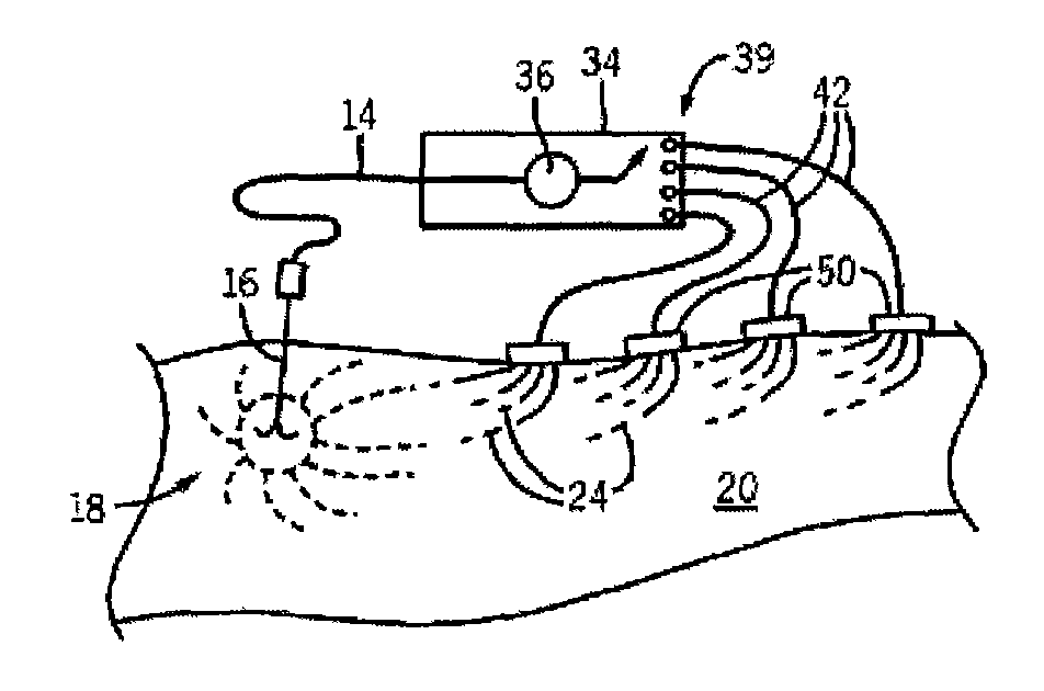
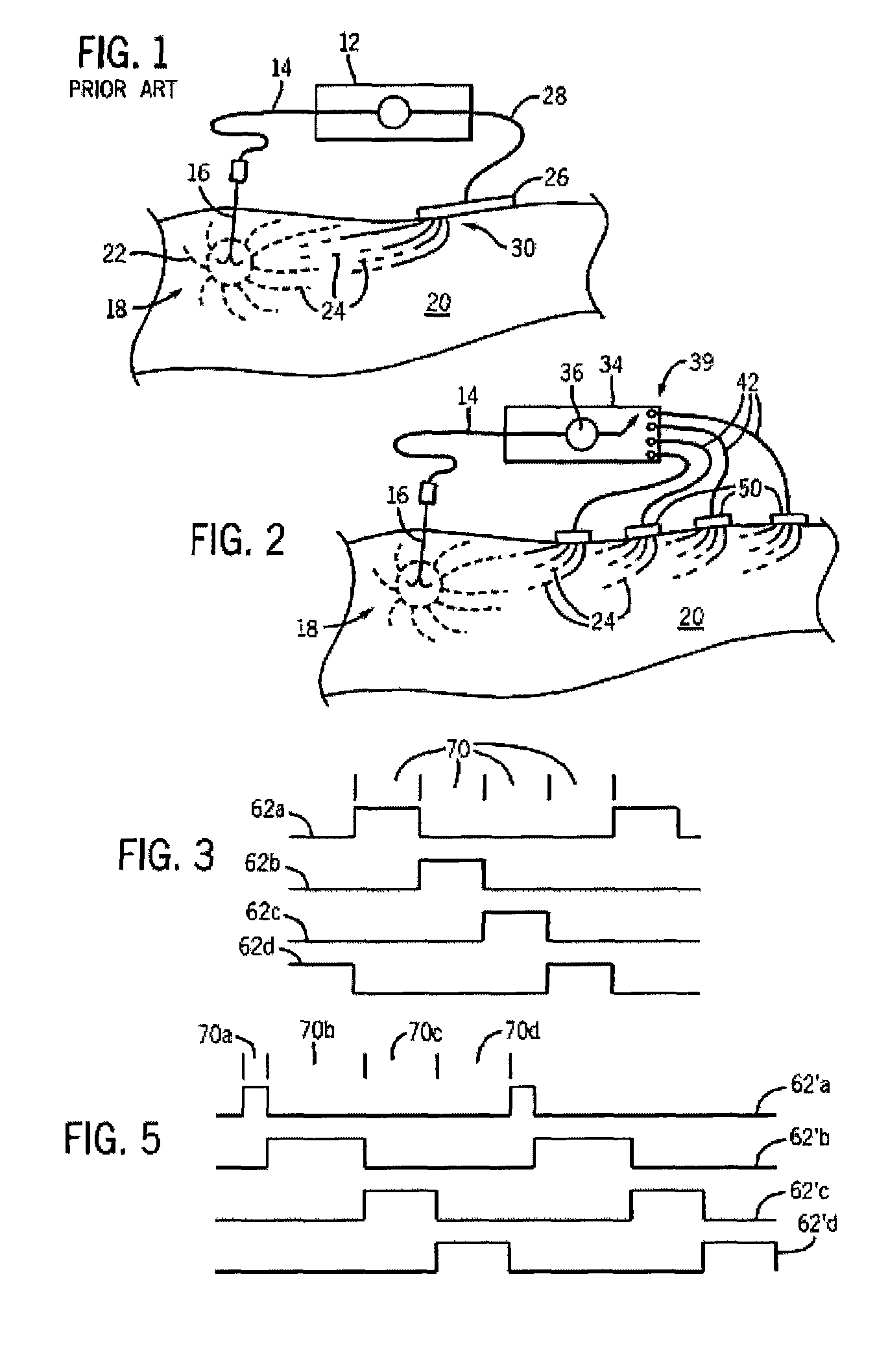
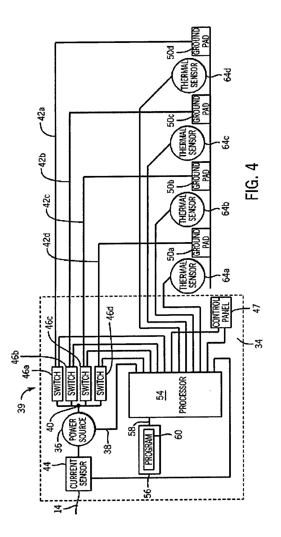
[0045]Referring now to FIGS. 2 and 3, in a first embodiment, the processor 54 may sequentially activate switches 46 to provide waveforms 62a through 62d as control signals for switches 46a through 46d, so that current flows through conductors 42a through 42d during the corresponding on-times of these waveforms. These waveforms 62a through 62d switch the flow of ablation current 24 between the end 18 of the ablation electrode 16 and one ground pad 50a through 50d at a time, rotating through each of the particular ground pads 50a through 50d before returning again to repeat this rotation. As shown in FIG. 3, the current flow on-time 70 on each of the conductors 42a through 42d may, in the first case, be equal dividing the total ablation-time, power and current by the number of ground pads 50a through 50d, in this example, four. Note, that this switching between ground pads 50a through 50d nevertheless provides continuous or near continuous current flow at the ablation electrode 16 and...

second embodiment

[0047]Referring now to FIG. 4, generally a single ground pad 50a, for example, may be closer to the ablation site 22 or there may be other local variation in the site of the ground pad 50a, for example, the presence or absence of large heat dissipating blood vessels or differences in the contact resistance between the ground pad 50a and the patient 20, that affect equal sharing of power among the ground pads 50a through 50d. Accordingly, in a second embodiment, the thermocouples 64a through 64d or other similar temperature measuring component associated with each of the ground pads 50a through 50d, may provide signals used by the processor 54 to further control the power to each of the ground pads 50a through 50d.

[0048]The switching between different ground pads 50 should not produce significant stimulation of excitable tissues like nerves, muscle, and heart which can be excited by low frequency signals typically below approximately 100 kHz. To avoid excitation, the switching may b...


PUM


Abstract

A radiofrequency ablation system provides multiple ground pads and active control of current flow through the ground pads to provide improved power sharing at the tissue near the ground pads reducing risk of patient skin burns for higher power ablation generators.

Description

CROSS-REFERENCE TO RELATED APPLICATIONS[0001]This application is a continuation of PCT Application Ser. No. US05 / 16172 filed May 9, 2005 entitled “Radiofrequency Ablation with Independently Controllable Ground Pad Conductors” which claims the benefit of U.S. Provisional application 60 / 569,896 filed May 11, 2004.STATEMENT REGARDING FEDERALLY SPONSORED RESEARCH OR DEVELOPMENT[0002]This invention was made with United States government support awarded by the following agencies: NIH DK058839. The United States has certain rights in this invention.BACKGROUND OF THE INVENTION[0003]The present invention relates to radio frequency ablation of tumors and the like, and in particular to a method using multiple ground pads, or multiple independent ground pad elements within a single pad, to reduce the risk of skin burns.[0004]Ablation of tumors, such as liver (hepatic) tumors, uses heat or cold to kill tumor cells. In radiofrequency ablation (RFA), an electrode is inserted into the tumor and cur...

Claims


Application Information

Patent Timeline
Patent Type & Authority Patents(United States)
IPC IPC(8): A61B18/18A61B18/12A61B18/14A61B18/16
CPCA61B18/1233A61B18/16A61B18/1477A61B2018/124A61B2018/1425A61B2018/165
Inventor LEE, JR., FRED T.WINTER, III, THOMAS CHARLESHAEMMERICH, DIETER GEORGSAMPSON, LISA ANNGOLDBERG, S. NAHUM
Owner WISCONSIN ALUMNI RES FOUND
Why Eureka
Try Eureka