
Quick-disconnect waterproof connector

a waterproof connector and quick-disconnect technology, applied in the field of pin and socket connectors, can solve the problems of escalating the risk of surroundings damage, and achieve the effects of easy assembly, easy assembly and long-term us

Active Publication Date: 2010-06-29
RECTORSEAL LLC
View PDF1 Cites 10 Cited by
  • Summary
  • Abstract
  • Description
  • Claims
  • Application Information

AI Technical Summary

Benefits of technology

[0006]The primary object of this invention is to provide a quick-disconnect connector for secure and waterproof connection of electrical wires to one another in series, in applications where water or other fluids may be present. Another object of this invention is to provide a quick-disconnect waterproof connector having rugged and durable construction for long-term use. It is also an object of this invention to provide a quick-disconnect waterproof connector the two parts of which are easily joined together, yet do not easily come apart unless separation is intended. It is a further object of this invention to provide a quick-disconnect waterproof connector that provides strain-relief accommodation for wiring connected to it, which also helps to achieve a waterproof seal for the electrically-conductive components within its over-molding. It is also an object of this invention to provide a quick-disconnect waterproof connector having an easily gripped exterior surface. Another object of this invention is to provide a quick-disconnect waterproof connector with low manufacturing cost.
[0007]The present invention, when properly made and used, will provide a quick-disconnect waterproof connector for secure connection of electrical wires to one another in series, in applications where water or other fluids may be present, such as but not limited to fluid-overflow monitoring applications related to air conditioning systems. The most preferred connector in the present invention has two identical elongated connective members each having a pin positioned adjacent to a socket in side-to-side array on one of its opposing ends, over-molding around the socket and much of the pin, with a plurality of external ribs laterally extending across the over-molding on opposed sides thereof, and further with the over-molding around the base of the pin having a tapered boss, the over-molding around the straight-walled open end of the socket configured for snugly receiving the tapered boss of the other elongated connective member to create a waterproof connection around the opposed pins and sockets that become joined, and the over-molding also having on the second one of its opposing ends a protective strain-relief extension positioned around the sheathed insulated wires as they enter into the over-molding. The strain-relief extension, in combination with a two-part wire terminal depending from the proximal end of each socket and pin, allows the electrical wiring of the present invention to remain securely connected to the socket and pin even when as much as eight pounds of force are applied to the wiring in an attempt to interrupt electrical communication between the wiring and the pins and sockets. The tapered boss pushes the straight wall bore adjacent to a paired socket in an outwardly direction to create an enhanced waterproof connection around the pins and sockets. In addition, the tapered boss also has a better lead-in chamfer into the straight wall bore of the over-molding extension around the distal end of the opposed socket so that low insertion installer-applied connection forces will allow the opposed connective members to become completely pressed together to make the proper and needed watertight connection and seal. The use of a tapered boss in combination a straight wall bore to create a watertight seal in this connection device, also permits larger manufacturing tolerances, providing decreased manufacturing costs

Problems solved by technology

This is vitally important for equipment used for water detection purposes, as a breakdown in communication between probes and switches only allows more fluid to accumulate, escalating the risk for damage to surroundings.

Method used


Image

  • Quick-disconnect waterproof connector
  • Quick-disconnect waterproof connector
  • Quick-disconnect waterproof connector

Examples


Embodiment Construction

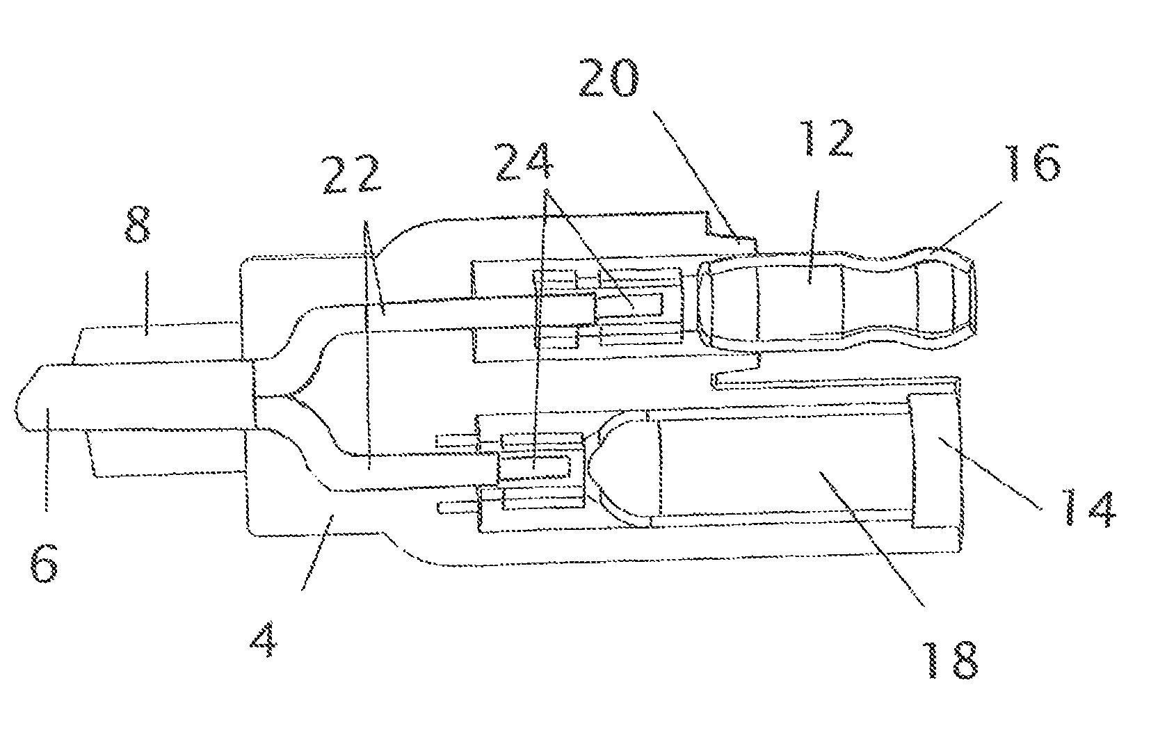
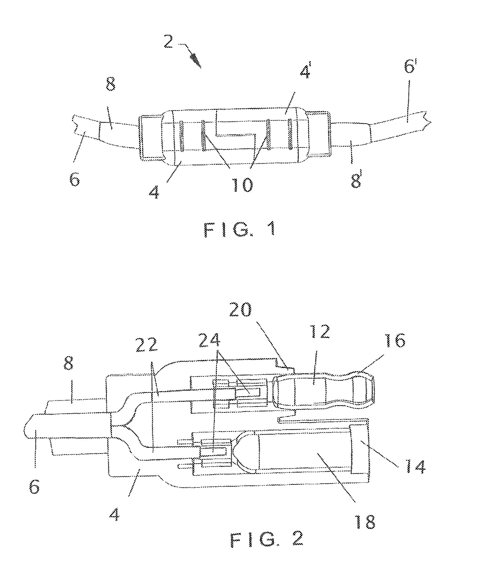
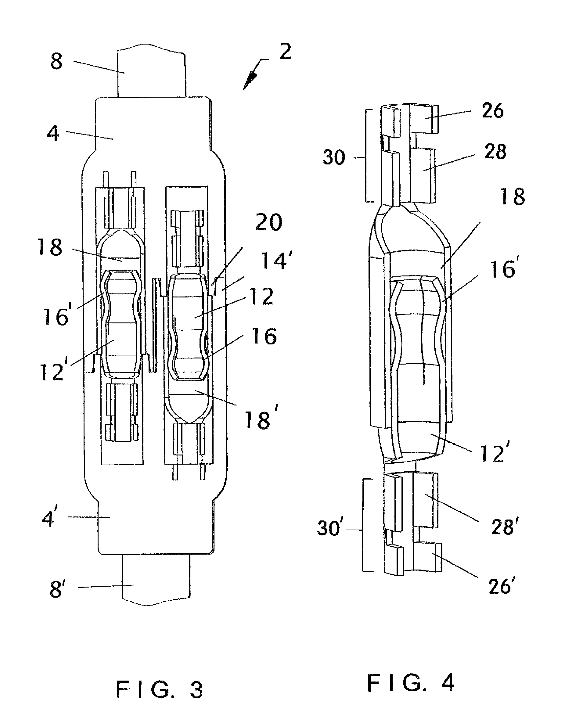
[0028]The present invention provides a quick-disconnect waterproof connector 2 that can be employed for secure connection of electrical wires 22 to one another in series, in applications where water or other fluids may be present. The most preferred connector 2 has two connective members each with over-molding (given the numbers of 4 and 4′ in the accompanying illustrations). Each connective member also has a pin 12 or 12′ positioned adjacent to a socket 18 or 18′ in side-to-side array, over-molding 4 and 4′ positioned around both the pins and sockets (12 / 12′ and 18 / 18′) with a plurality of external ribs 10 laterally extending across its exterior surface on both of its opposing sides. In addition, each connective member also has over-molding 4 or 4′ around the base of its pin 12 or 12′ that comprises a tapered boss 20 or 20′, with the over-molding 4 or 4′ around the open end of the socket 18 or 18′ configured as an extension 14 or 14′ that snugly receives the tapered boss 20 or 20′ ...


PUM


Abstract

A quick-disconnect waterproof connector for secure connection of electrical wires to one another in series, in applications where water or other fluids may be present. The most preferred connector has two connecting members each with opposing ends, a pin adjacent to a socket in side-to-side array at a first of said opposing ends, over-molding around the pin and socket, a plurality of external ribs laterally extending across the over-molding on opposing sides thereof, the over-molding around the base of the pin having a tapered boss, the over-molding extension around the distal end of the socket configured for snugly receiving the tapered boss of its paired member to create a waterproof connection, two sheathed insulated wires each connected to one of the contacts, and the over-molding also having on its second end a strain-relief extension positioned around the sheathed insulated wires as they enter the over-molding.

Description

CROSS-REFERENCES TO RELATED APPLICATIONS[0001]This application is a continuation-in-part of a previously filed and currently pending U.S. utility patent application to the same inventor, which was given the Ser. No. 12 / 565,765, was filed on Sep. 24, 2009, and has overlapping subject matter to that in the new patent application now being filed. The previously filed and currently pending U.S. utility patent application from which domestic priority for the instant patent application herein is desired also has a title of “Water Detection Assembly for Primary Drain Lines” and an. Since the quick-disconnect connector disclosed herein is one of components in the water detection assembly invention disclosed in the previously filed and currently pending U.S. Patent application identified hereinabove, and the applicant has filed this new patent application in an attempt to receive patent protection solely for the quick-disconnect connector component thereof, domestic benefit based upon this p...

Claims


Application Information

Patent Timeline
Patent Type & Authority Patents(United States)
IPC IPC(8): H01R13/52
CPCH01R23/27H01R13/52H01R4/184H01R24/84
Inventor CANTOLINO, CHRISTOPHER RALPH
Owner RECTORSEAL LLC
Learn More