
Extension tube for concrete floor boxes

a technology of extension tubes and floor boxes, applied in the field of electric boxes, can solve the problems of affecting the quality of concrete floor boxes, and requiring complicated assemblies, etc., and achieves the effect of reducing the number of floor boxes, and improving the quality of concr

Active Publication Date: 2011-09-20
THOMAS & BETTS INT INC
View PDF25 Cites 7 Cited by
  • Summary
  • Abstract
  • Description
  • Claims
  • Application Information

AI Technical Summary

Benefits of technology

The extension tube allows for easy adjustment to accommodate different concrete floor thicknesses, prevents side wall deformation, and ensures secure anchoring without adhesives, reducing installation time and tooling costs while maintaining a consistent interior space for electrical connections.

Problems solved by technology

One of the problems in positioning a floor box is that the installer must assure that the top of the floor box is both flush and level with the top of the poured floor in which it is set.
However, these cuttable floor boxes have certain disadvantages.
Furthermore, many of these cuttable floor boxes require complicated assemblies to assure that the terminations housed at the upper end of the box are level with the concrete floor.
Loose pieces of concrete and other debris in the area have a tendency to back-fill into the space between the flexed wall of the box and the concrete floor.
As a result of the collection of debris in the space, the wall of the box assumes a permanent internal bow or deformation, which can make internal adjustment of the box difficult to accomplish.
Also, internal bowing reduces the useable interior space and makes it more difficult for the installer to make connections inside the box.
This problem is especially prevalent in plastic rectangular floor boxes where the elongate side walls have a greater tendency to bow or flex either when sawed or due to the force of the poured concrete on the outside wall.
At the present time, there is no approved method for the installation of electrical boxes in thick concrete slabs, such as post-tensioned slabs.

Method used


Image

  • Extension tube for concrete floor boxes
  • Extension tube for concrete floor boxes
  • Extension tube for concrete floor boxes

Examples


Embodiment Construction

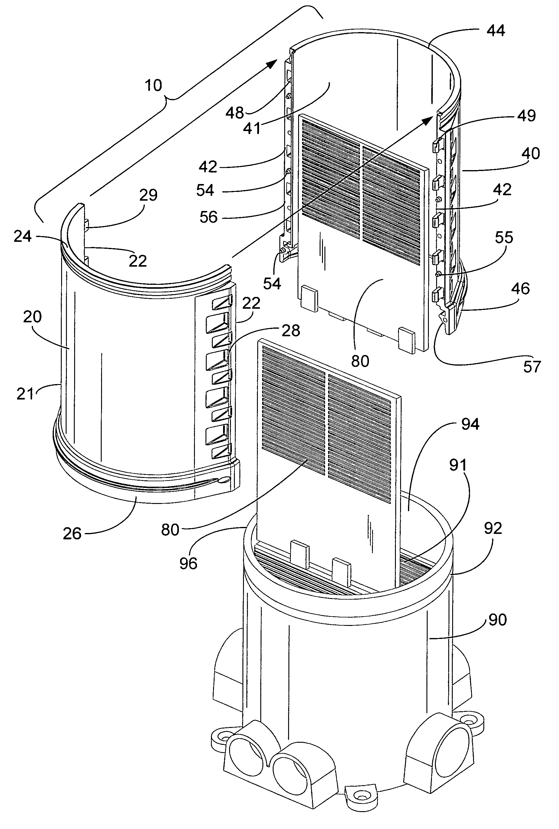
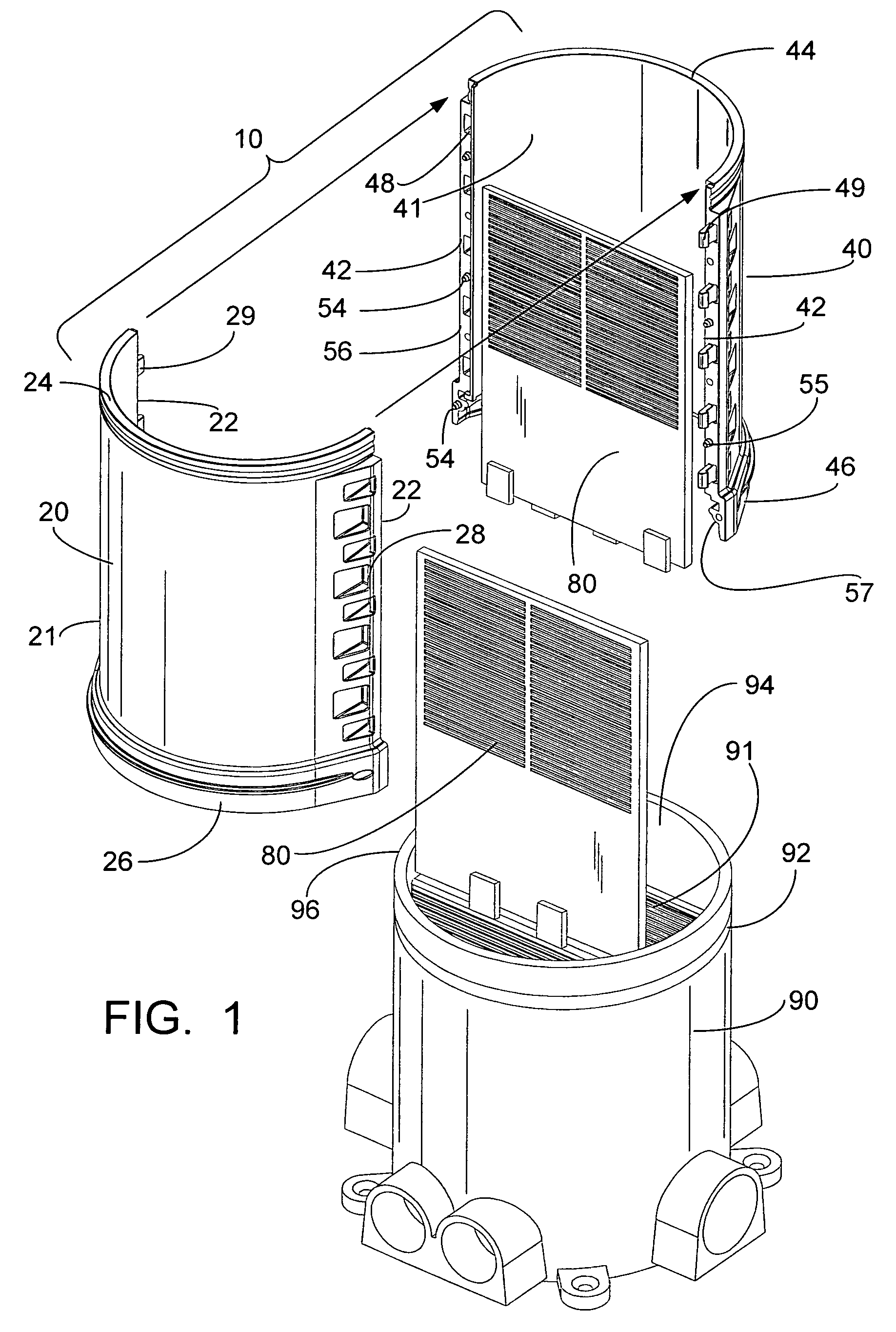
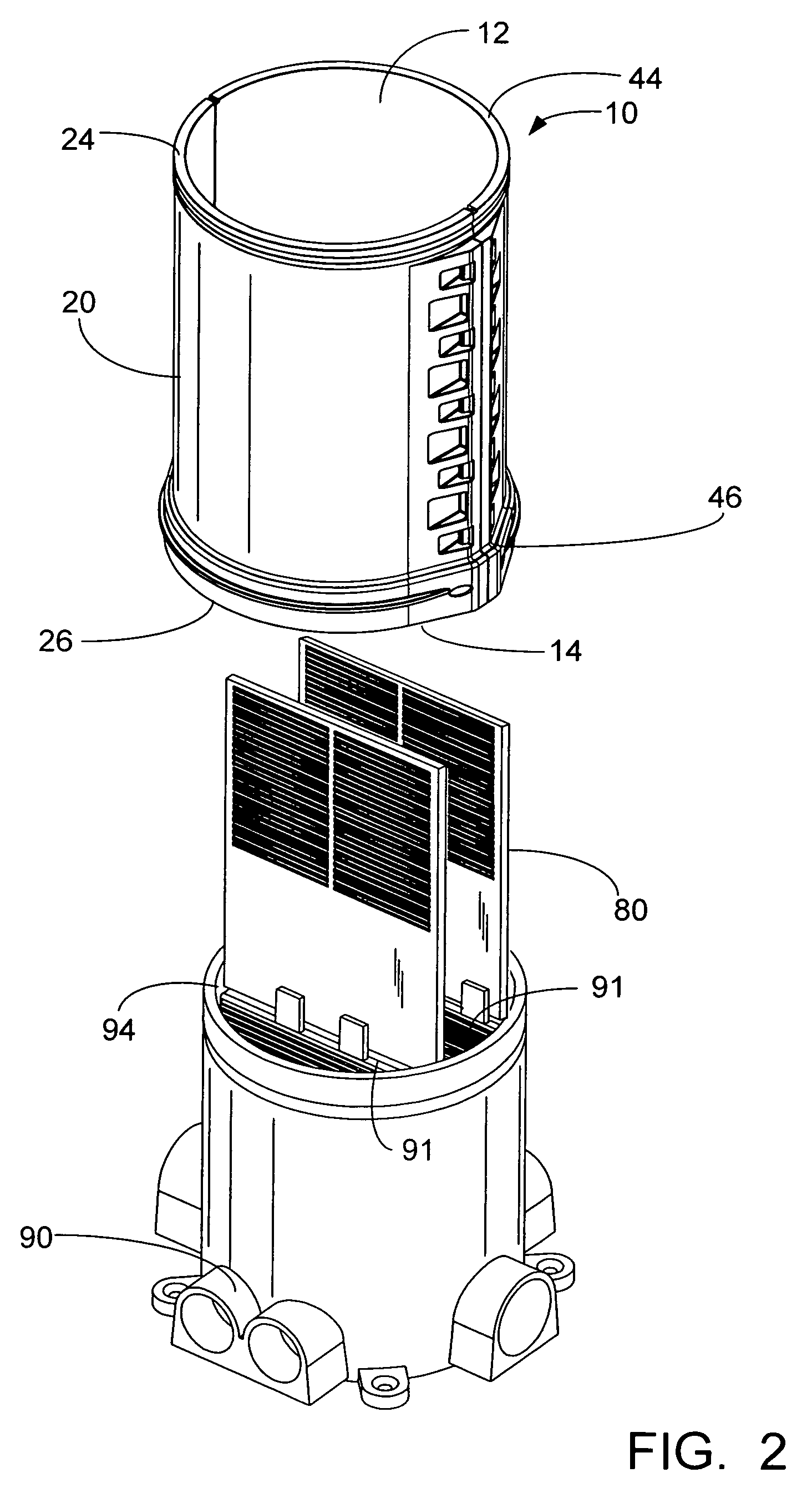
[0032]The present invention is an extension tube for an electrical floor box that is formed by first and second sections. Each section has a curved wall with an interior surface and an exterior surface, a top end, a bottom end, a top portion, a bottom portion and a pair of side edges. For the present disclosure, the extension tube is described as cylindrically-shaped. However, one skilled in the art would understand that the wall does not have to be curved and can be formed in other shapes so that, when the sections are joined together, the extension tube is square, rectangular, hexagonal, octagonal or oval in shape. The bottom portion is offset outwardly from the top portion, thereby creating a ledge. When the two sections are joined together to form the extension tube, the top portion has a ring groove on the exterior surface and the bottom portion has a snap ring on the interior surface. In some embodiments, this is reversed so that the top portion has a snap ring on the exterior...


PUM


Abstract

An extension tube for an electrical floor box that includes a first section and a second section. Each section has a curved wall with an interior surface and an exterior surface, a top portion, a bottom portion and first and second side edges. The bottom portion is offset radially outwardly from the top portion by a ledge and the side edges have connecting mechanisms which join the two sections together to form the extension tube. The extension tube includes a top portion and a belled bottom portion which are formed so that the top portion of one extension tube can be inserted into the bottom portion of another extension tube.

Description

[0001]This application claims priority from provisional application Ser. No. 61 / 063,600, filed on Feb. 5, 2008, which is incorporated herein in its entirety.FIELD OF THE INVENTION[0002]The present invention relates to electrical boxes installed in concrete floors. In particular, the present invention relates to extension tubes that allow a standard size electrical box to be installed in floors having different thicknesses.BACKGROUND OF INVENTION[0003]The use of an electrical junction or outlet box to accommodate electrical cable terminations is well known in the art. These boxes typically house electrical components, such as electrical receptacles, jacks and plugs and other devices. The junction box permits the electrical cables to either pass through or connect to the electrical components housed inside the box. In certain applications, these junction boxes are used in floor installations, and are referred to as floor boxes. Electrical cable distribution takes place beneath the sur...

Claims


Application Information

Patent Timeline
Patent Type & Authority Patents(United States)
IPC IPC(8): H02G3/18H02G3/08
CPCH02G3/0493H02G3/185H02G3/086
Inventor JOLLY, ROBERT K.
Owner THOMAS & BETTS INT INC
Learn More