Combined illumination and ventilation duct

a ventilation duct and combined technology, applied in the field of ducts, can solve the problems of increasing installation space, complicated installation and design, complicated wiring, etc., and achieve the effects of reducing installation and occupied spaces, easy joining together, and facilitating installation and arrangemen

Active Publication Date: 2006-11-23
LG ELECTRONICS INC
View PDF4 Cites 5 Cited by
  • Summary
  • Abstract
  • Description
  • Claims
  • Application Information

AI Technical Summary

Benefits of technology

[0012] An object of the present invention is to provide a combined illumination and ventilation duct, by which installation and occupied spaces can be reduced by enabling simultaneous illumination and ventilation.
[0013] Another object of the present invention is to provide a combined illumination and ventilation duct, by which installation and arrangement are facilitated by enabling several ducts to be easily joined together.

Problems solved by technology

However, the related art illuminator and ventilator have the following problems.
And, wiring becomes very complicated.
So, an installation space increases and the installation and design become more complicated.

Method used


Image

  • Combined illumination and ventilation duct
  • Combined illumination and ventilation duct
  • Combined illumination and ventilation duct

Examples


first embodiment

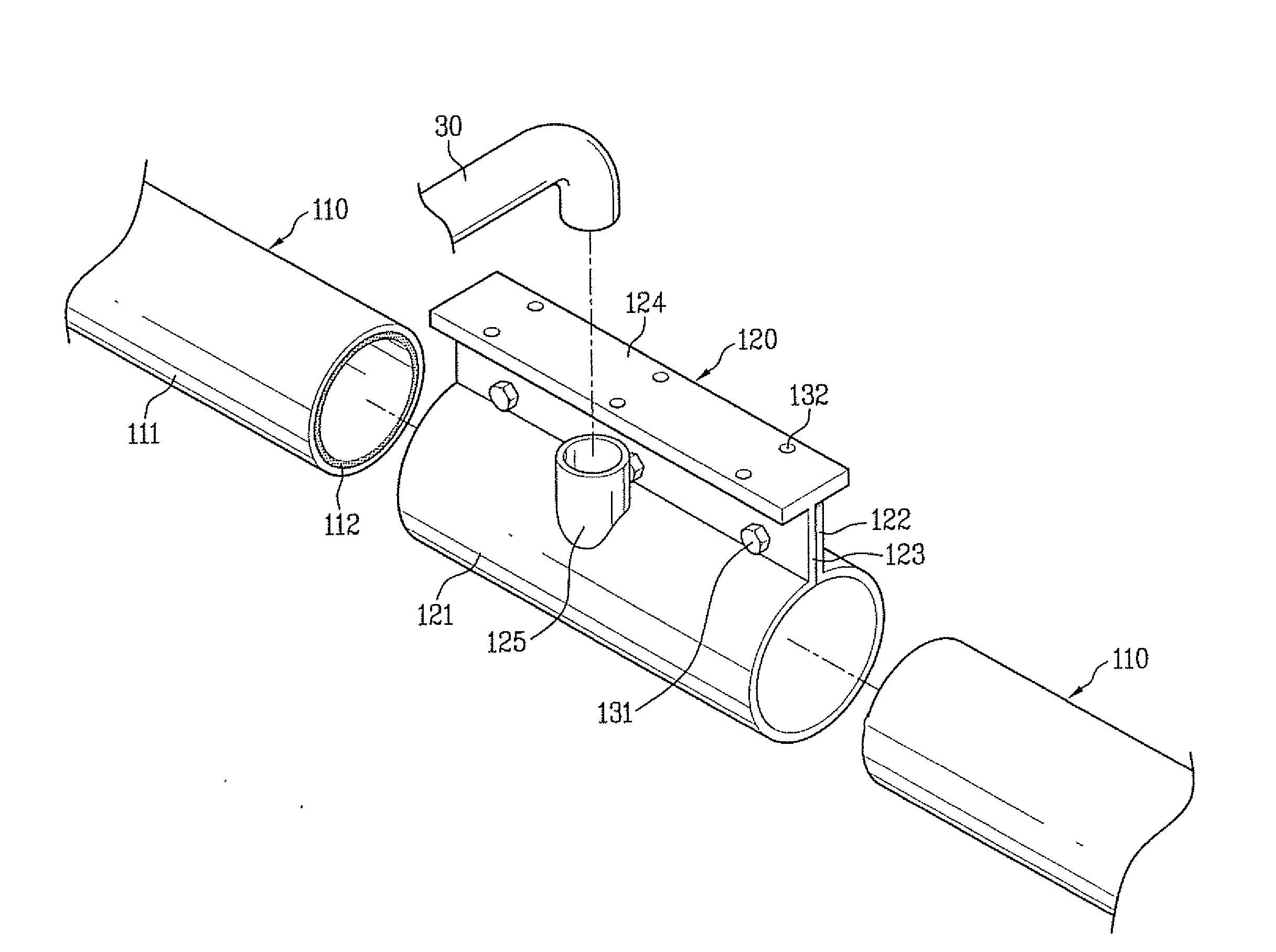
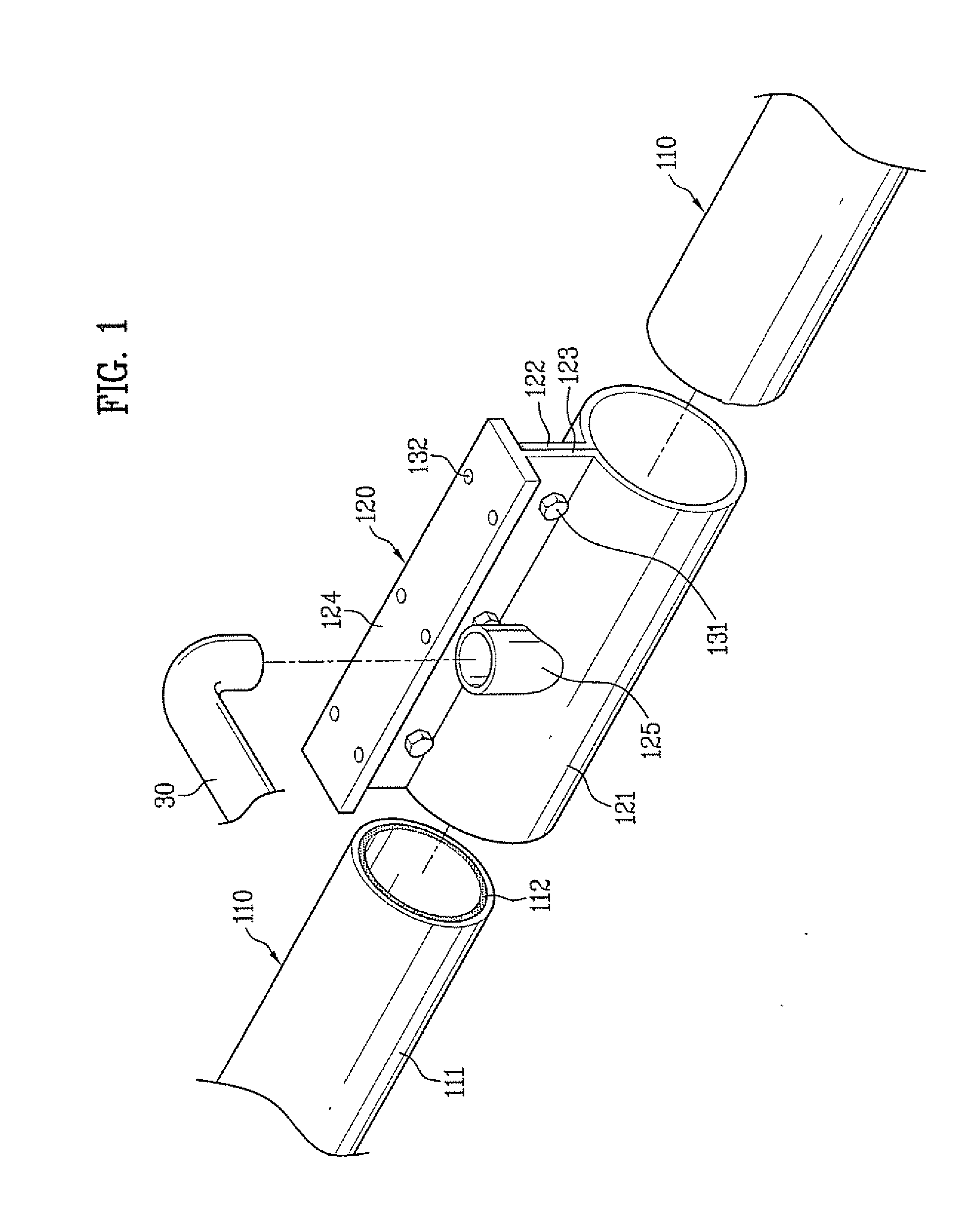
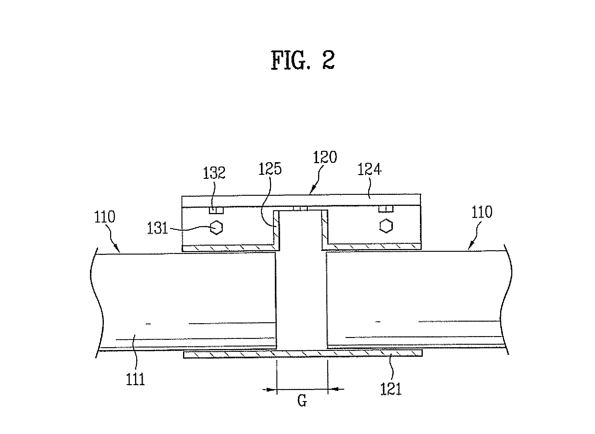
[0046]FIG. 1 is an exploded perspective diagram of a combined illumination and ventilation duct according to the present invention and FIG. 2 is a cross-sectional diagram of the duct shown in FIG. 1.

[0047] A configuration of a combined illumination and ventilation duct according to a first embodiment of the present invention is explained in detail with reference to FIG. 1 and FIG. 2 as follows.

[0048] Referring to FIG. 1 and FIG. 2, a combined illumination and ventilation duct according to a first embodiment of the present invention includes at least two optical pipes 110 and at least one connector 120 connecting the at least two optical pipes 110 together.

[0049] Each of the at least two optical pipes 110 includes a tube 111 formed of a light-transmittable material such as a synthesized resin, and more particularly, an acryl based material, and a total reflection layer 112 formed on an inner circumference of the tube 111.

[0050] Since the total reflection layer 112 reflects light t...

second embodiment

[0062] Referring to FIG. 3 and FIG. 4, a combined illumination and ventilation duct according to the present invention includes at least two connected optical pipes 210 and a connector 220. A reference number 211 in FIG. 3 or FIG. 4 denotes a tube corresponding to the former tube 111 and a reference number 212 denotes a total reflection layer corresponding to the former total reflection layer 112. A reference number 221 denotes a body of the connector 220 corresponding to the former body 110. Reference numbers 222 and 223 denote first and second extensions of the connector 220 corresponding to the firmer first and second extension 122 and 123, respectively. A reference number 224 denotes a support of the connector 220 corresponding to the former support 124. And, a reference number 225 denotes a connecting nipple of the connector 220 corresponding to the former nipple 125.

[0063] At least one projection 213, as shown in FIG. 3 and FIG. 4, is formed on an outer circumference of an end...


PUM


Abstract

A combined illumination and ventilation duct is disclosed. The present invention includes at least two optical pipes having air flown inside wherein light proceeds within the at least two optical pipes by being totally reflected and a connector connecting the at least two optical pipes together, the connector having a connecting nipple to be connected to a pipe. An upper part of the duct is embedded in a fake ceiling under a real ceiling and a lower part is exposed under the fake ceiling. Alternatively, the whole combined illumination and ventilation duct is installed to be exposed under the fake ceiling. As air and light pass through the combined illumination and ventilation duct, the light is totally reflected within the optical pipes to illuminate an indoor space and the air is supplied or discharged to ventilate the indoor space.

Description

[0001] This application claims the benefit of the Korean Patent Application No. P2005-42497, filed on May 20, 2005, which is hereby incorporated by reference as if fully set forth herein. BACKGROUND OF THE INVENTION [0002] 1. Field of the Invention [0003] The present invention relates to a duct, and more particularly, to a combined illumination and ventilation duct. Although the present invention is suitable for a wide scope of applications, it is particularly suitable for illuminating and ventilating an indoor space. [0004] 2. Discussion of the Related Art [0005] Generally, various ventilators for indoor space ventilation and various illuminators for providing predetermined intensity of illumination to an indoor space are installed in houses, large buildings and factory facilities. [0006] A ventilator consists of a duct on a ceiling of an indoor space to form a moving passage of air and a fan module sucking / blowing air into / from the duct. And, the ventilator may further consist of ...

Claims


Application Information

Patent Timeline
Patent Type & Authority Applications(United States)
IPC IPC(8): G02B6/00
CPCB63B45/06B63J2/04F21S11/00F21V2200/40F24F13/078F24F2221/02Y02T70/72F21V33/0088Y02T70/00F24F7/00F24F13/00
Inventor CHOI, KEUN HYOUNGCHOI, IN HOCHOI, DONG WHANCHOI, HO SEON
Owner LG ELECTRONICS INC
Why Eureka
Try Eureka