Hybrid drive for an aircraft

a hybrid drive and aircraft technology, applied in combination engines, machines/engines, combination engines, etc., to achieve the effect of low pollutant discharg

Inactive Publication Date: 2009-12-03
AIRBUS OPERATIONS GMBH
View PDF8 Cites 44 Cited by
  • Summary
  • Abstract
  • Description
  • Claims
  • Application Information

AI Technical Summary

Benefits of technology

[0007]Among other things, it may be an object of the present inve

Problems solved by technology

In addition, the current civil commercial aircraft have come to a point in their improvement potenti

Method used


Image

  • Hybrid drive for an aircraft
  • Hybrid drive for an aircraft
  • Hybrid drive for an aircraft

Examples


Embodiment Construction

[0038]Identical or similar components in different figures are provided with identical reference numerals. The illustrations in the figures are schematic and are not to scale.

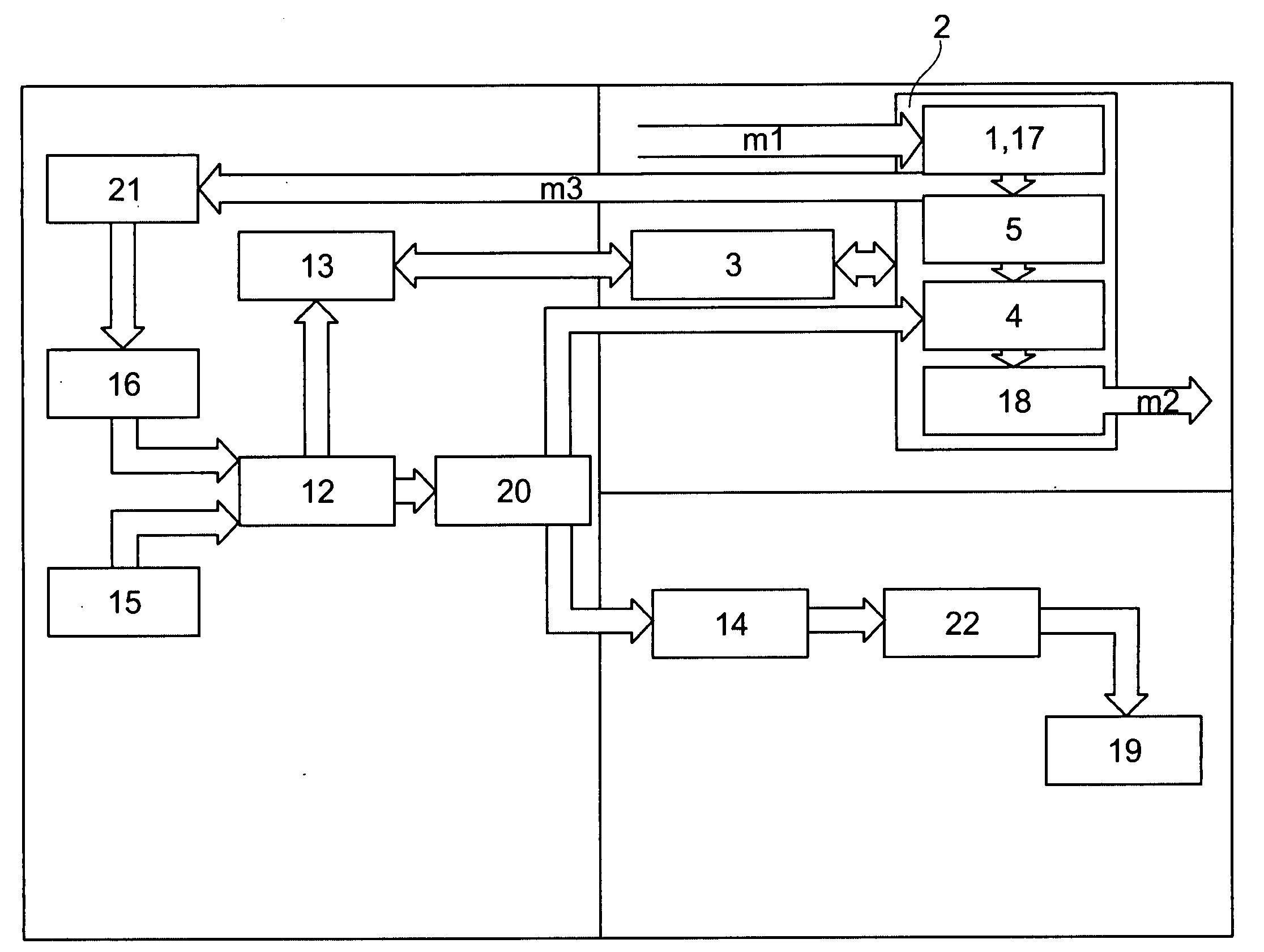
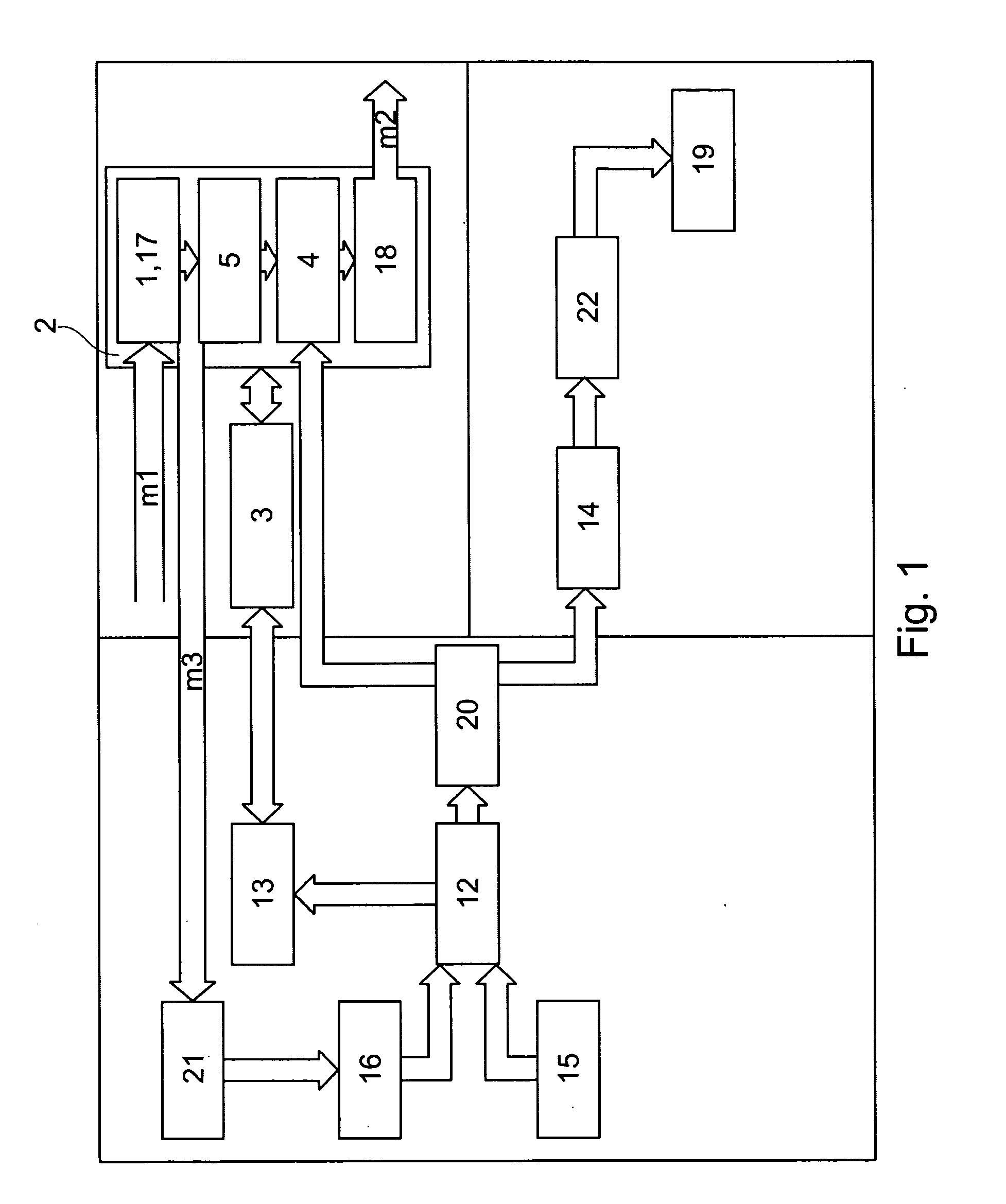
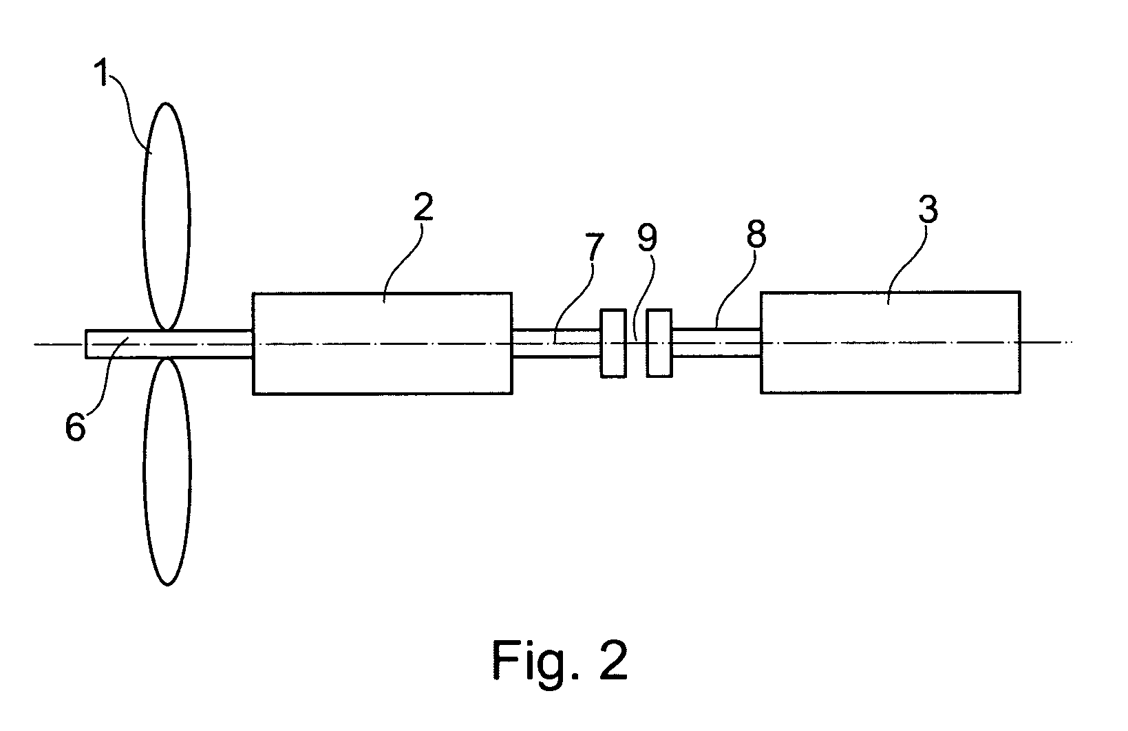
[0039]FIG. 1 shows an exemplary embodiment of the drive device for an aircraft. The drive device comprises a drive unit 1, a gas turbine apparatus 2 for generating a first drive energy, and an electric motor 3 for generating a second drive energy. The gas turbine apparatus 2 and the electric motor 3 are set up in such a way that the drive unit 1 may be provided with at least one of the first drive energy and the second drive energy. The drive unit 1 is set up to generate propulsion using at least one of the first drive energy and the second drive energy.

[0040]Furthermore, the drive device comprises a water injection apparatus 4. The gas turbine apparatus 2 comprises a combustion chamber 5, from which a compressor stage 17 is connected downstream, and a turbine stage 18. For example, the water injection apparatu...


PUM


Abstract

A drive device for an aircraft comprises a gas turbine apparatus for generating a first drive energy and electric motor for generating a second drive energy. The gas turbine apparatus and the electric motor are set up in such a way that the drive unit may be provided with at least one of the first drive energy and the second drive energy. The drive unit is set up to generate propulsion using at least one of the first drive energy and the second drive energy.

Description

CROSS-REFERENCE TO RELATED APPLICATIONS[0001]This application claims the benefit of the filing date of U.S. Provisional Patent Application No. 60 / 861,666 filed Nov. 29, 2006, the disclosure of which is hereby incorporated herein by reference.BACKGROUND OF THE INVENTION[0002]The present invention relates to a drive device for an aircraft, a method for driving an aircraft, as well as the use of a drive device in an aircraft and an aircraft having a drive device.[0003]The percentage of air traffic currently makes up a small percentage of the worldwide petroleum consumption and air pollution. However, this percentage increases with the reduction of other air-contaminating modes of transport and the increase of air traffic. In addition, the current civil commercial aircraft have come to a point in their improvement potential and development potential at which slight improvements may be achieved only by very great effort.[0004]Therefore, the attempt is being made either to make the harmfu...

Claims


Application Information

Patent Timeline
IPC IPC(8): F02C6/18F02B73/00F02C7/00
CPCB64D27/02B64D27/24Y02T50/64Y02T50/44B64D2027/026Y02T50/40Y02T50/60
Inventor HOFFJANN, CLAUSSCHULDZIG, HANSGEORGWESTENBERGER, ANDREAS
Owner AIRBUS OPERATIONS GMBH
Why Eureka
Try Eureka