[0013] The invention is based on the concept of providing a double-loop structure for the
power control device. The wind energy installations of the wind farm are divided into at least two groups, which are driven differently by the wind farm master. The wind energy installations of the second group are connected to a controller, which conventionally responds relatively slowly to changes in power. The wind energy installations of the first group, on the other hand, are connected to a fast loop, whose controller has a higher dynamic. It is thus possible to respond quickly to changes in desired values or to faults by acting on the wind energy installations of the first group. The steady-state accuracy over a relatively long period of time is in this case ensured by the wind energy installations of the second group which are connected to the slow channel. In this way, the invention combines the advantages of fast control with respect to the fast correction of faults or jumps in desired values with those of a slower control, such as the resistance to vibrations. By splitting the power control device into two control loops with different dynamics according to the invention (also referred to below as the slow and fast controllers), this is possible in an astonishingly simple manner. Complex controller concepts are not required for this purpose. The invention can also be realized with good results even with comparatively simple controller concepts, such as P controllers or PI controllers.
[0014] Expediently, the fast and the slow loop of the control device are cascaded. Cascaded is in this case understood to mean that an output
signal of the fast controller is used as an input
signal for the slow controller. This has the
advantage that only one
reference variable needs to be applied to the multi-loop controller according to the invention. The complexity in terms of circuitry is thus reduced. Furthermore, it has the
advantage over separate
reference variable inputting that there is no longer any need for mutual matching of the separate reference variables. The risk of instabilities owing to reference variables which have not been matched to one another or even contradict one another, such as may occur in the case of reference variables being applied separately, is thus avoided. A further
advantage here is the fact that, ideally, the desired value for the slow controller therefore has no mean value. The
reference variable behavior of the slow controller can therefore be optimized for steady-state accuracy around the zero position. Furthermore, the fast controller can preferably be designed to compensate for faults (or transients, desired-value jumps).
[0015] It is particularly expedient to design the multi-
loop control device according to the invention as a wattless power control device. For the true power, in this case a dedicated control device is provided which may have any desired design. Precisely in the case of wattless power control devices, it is important for maintaining a high degree of
system quality that they are designed to respond fast. With the wattless power control device according to the invention, owing to the multi-loop structure it is possible to respond particularly rapidly to changes, faults, etc. Therefore, thanks to the invention, even stringent requirements of the
system operator can be met with a comparatively low degree of complexity. With the multi-loop structure and its fast loop, the invention takes advantage of the particular properties of the wattless power that it has no mechanical equivalent. The invention has recognized that a fast control loop can therefore be formed which can respond to fast changes in the manipulated variable “wattless power”, without the risk of the
mechanical system being damaged or impaired (for example owing to overload as a result of a sudden fluctuating load). The fast loop can therefore be optimized individually to a good wattless power interference characteristic without needing to compromise with respect to steady-state accuracy. With the multi-loop structures according to the invention, this advantage can be used fully.
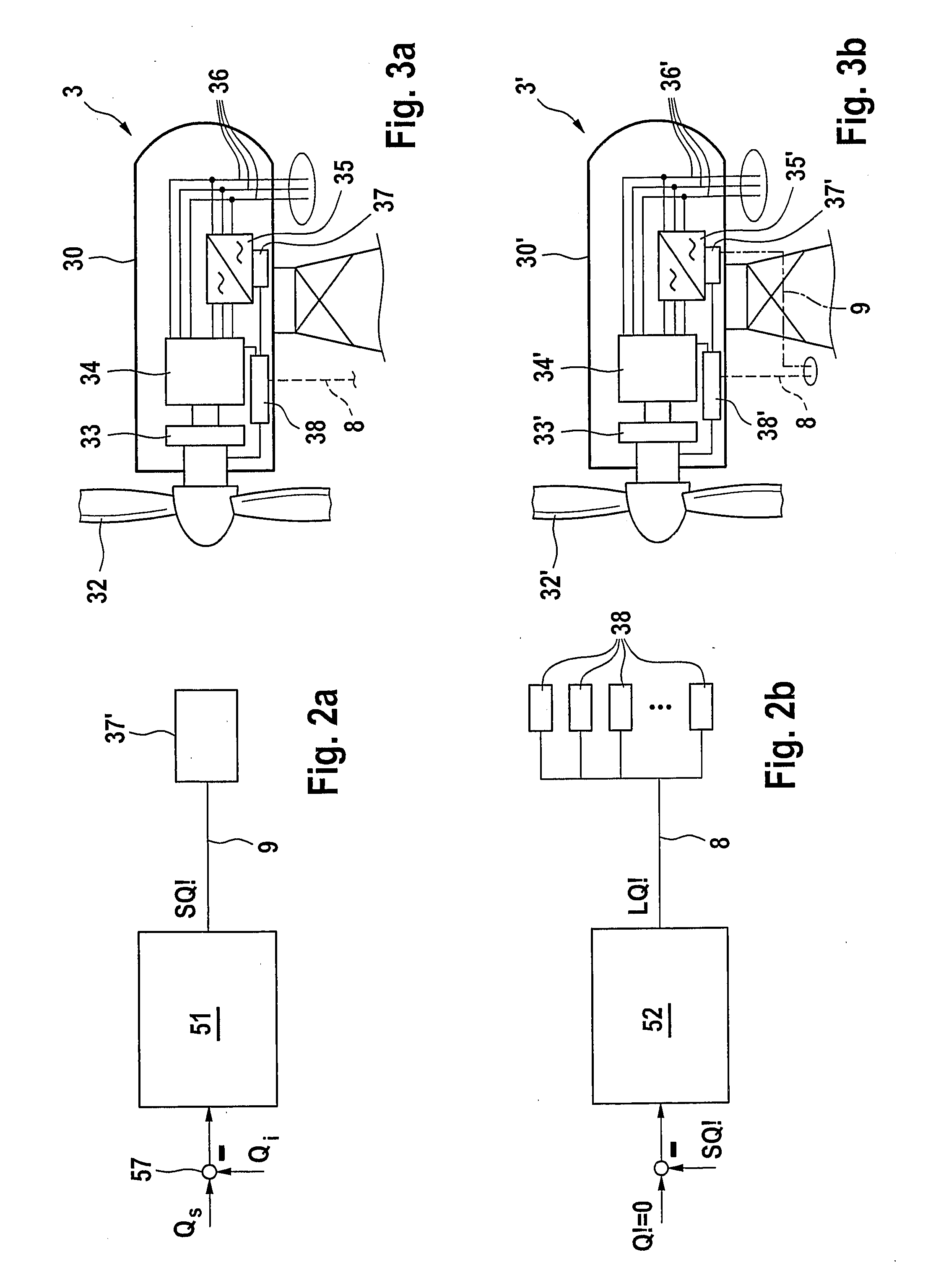
[0016] Preferably, the fast controller is connected so as to act directly on the
converters of the wind energy installations of the first group. Act directly in this case is understood to mean that the operational control of the individual wind energy installations is at least functionally avoided. This means that
delay times are minimized. The
converters can respond quickly to changed manipulated variables of the fast controller. This results in an improved response of the entire wind farm in the event of faults or desired-value jumps. The direct connection can be established in various ways. One advantageous possibility consists in connecting the output of the fast controller, via a dedicated
transmission channel, to the
converters of the wind energy installation of the first group. The dedicated
transmission channel may be, for example, a
dedicated line. Such an embodiment using individual wire technology has the advantage of having a simple and clear concept; it also guarantees short transfer times and therefore short response times. One
disadvantage, however, is the comparatively high degree of complexity. In order to reduce this, however, provision may also be made for a separate high-speed data network to be connected to the output of the fast controller and for it to be connected to the converters of the wind energy installations of the first group. High speed is in this case understood to mean that the data network has a higher transmission speed for the data present at the output of the fast controller than the data network used for other communication in the wind farm. With such a high-speed network, a reduction in the
transmission time can likewise be achieved as in the case of individual wire technology, but with reduced installation complexity. Preferably, the high-speed data network is provided with a real-time capability.
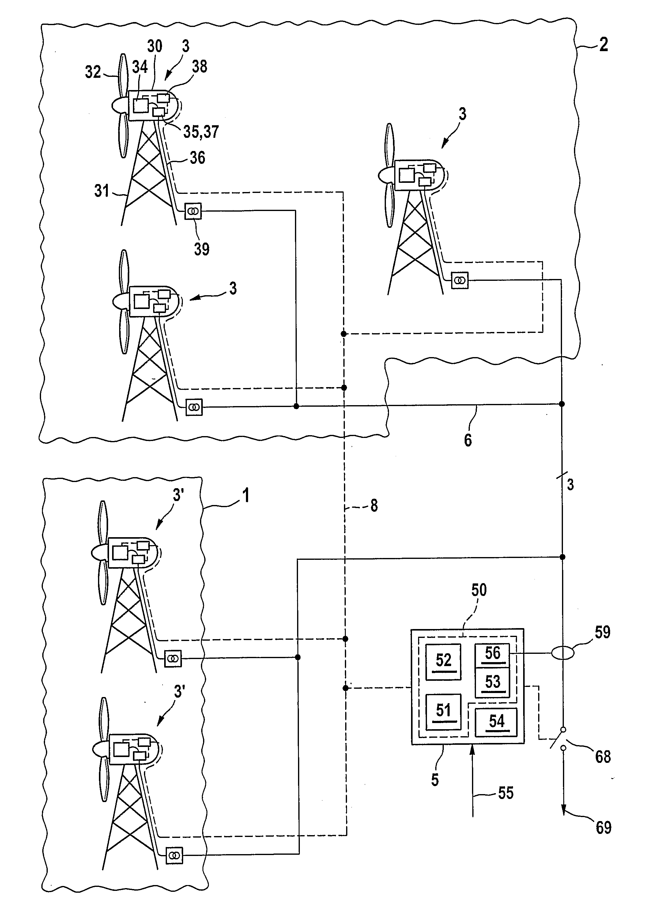
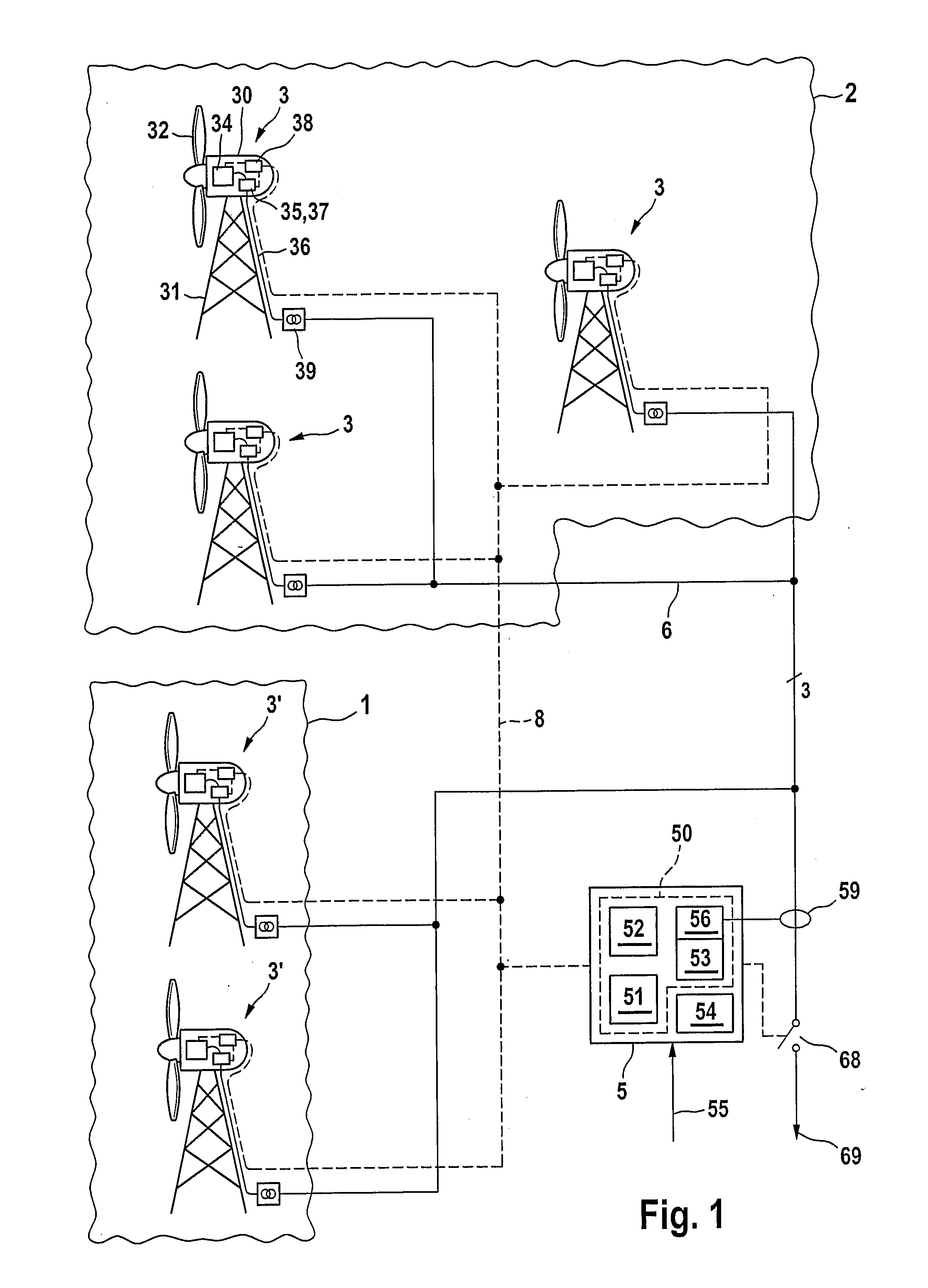
[0017] In order to further improve the control behavior, provision may be made for the wind energy installations of the first group to be arranged electrically close to the connection point to the power supply system. Electrically close is in this case understood to mean that the distance between the connection lines and the respective wind energy installations is as short as possible. In general, the
electrical distance follows the physical distance, but deviations may result from detours in the guidance of the line. The
electrically short arrangement means that actuating signals of the fast controller only need to be transferred over a short path and therefore are applied quickly to the converters of the wind energy installations of the first group. Furthermore, subsequent changes in the
power output of this wind energy installation become effective quickly at the connection point. This results in a
dual effect with respect to the shortening of the
response time.
[0019] In accordance with one further aspect of the invention, which is possibly used for independent protection, a wind farm is provided with a plurality of wind energy installations, which generate electrical energy to be output to a power supply system, and a wind farm master for controlling the wind energy installations, the wind energy installations having a generator, which is driven by means of a rotor, and the wind farm master having a
power controller, the wind energy installations being split into a first and a second group, the controller being part of a slow loop, which acts on the second group, of a multi-loop structure, which also has a fast loop, which acts on the second group. With this control loop structure, in contrast to the abovementioned embodiments, the wind farm master is not responsible for the fast loop for the first group of wind energy installations. Expediently, the fast loop is autonomous. This can advantageously be achieved by virtue of the fact that a corresponding control functionality is integrated in the control device of one of the wind energy installations of the first group. Such an embodiment is particularly advantageous when the first group comprises only a single wind energy installation. This makes possible not only an uncomplicated construction, but also a good
operational behavior thanks to short transfer times. It is therefore easily possible to design the fast loop such that it acts directly on the converter of the wind energy installation. It goes without saying that in this aspect of the invention as well, the wind energy installation of the fast loop is arranged as close as possible to the connection point.

