
Vertically curved face putter with multiple horizontal contact facets

Inactive Publication Date: 2010-07-06
JOHNSON LANNY L
View PDF49 Cites 14 Cited by
  • Summary
  • Abstract
  • Description
  • Claims
  • Application Information

AI Technical Summary

Benefits of technology

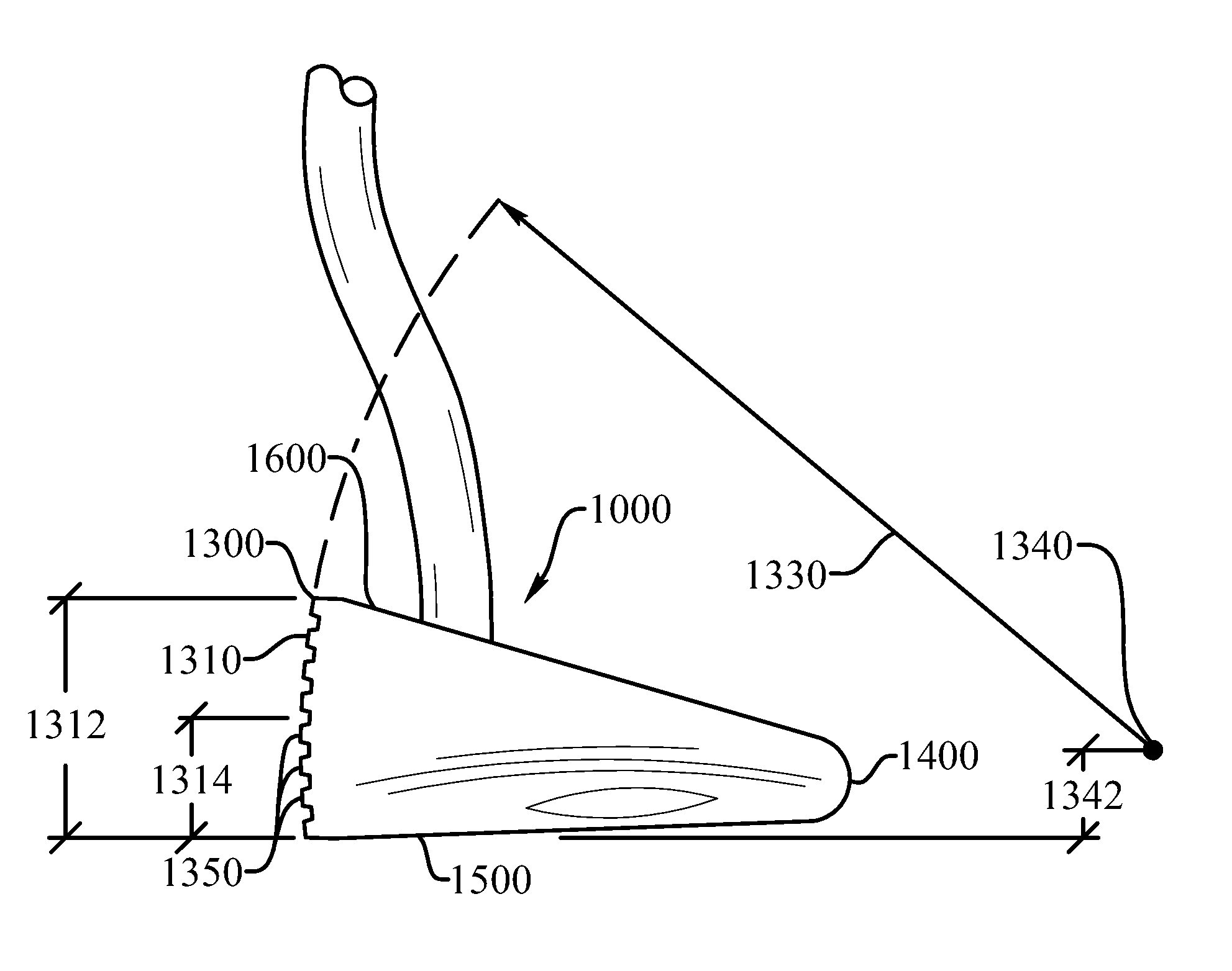
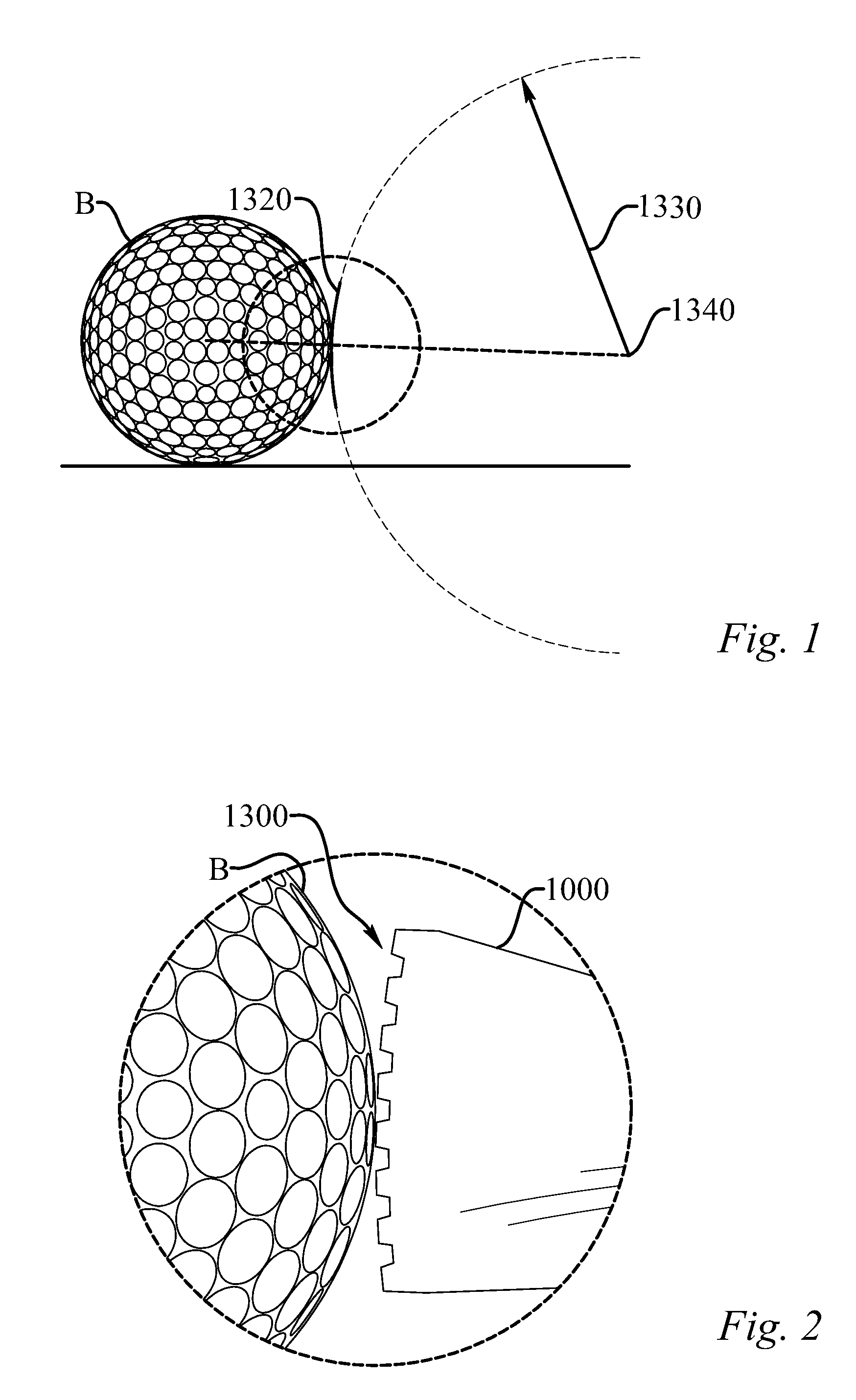
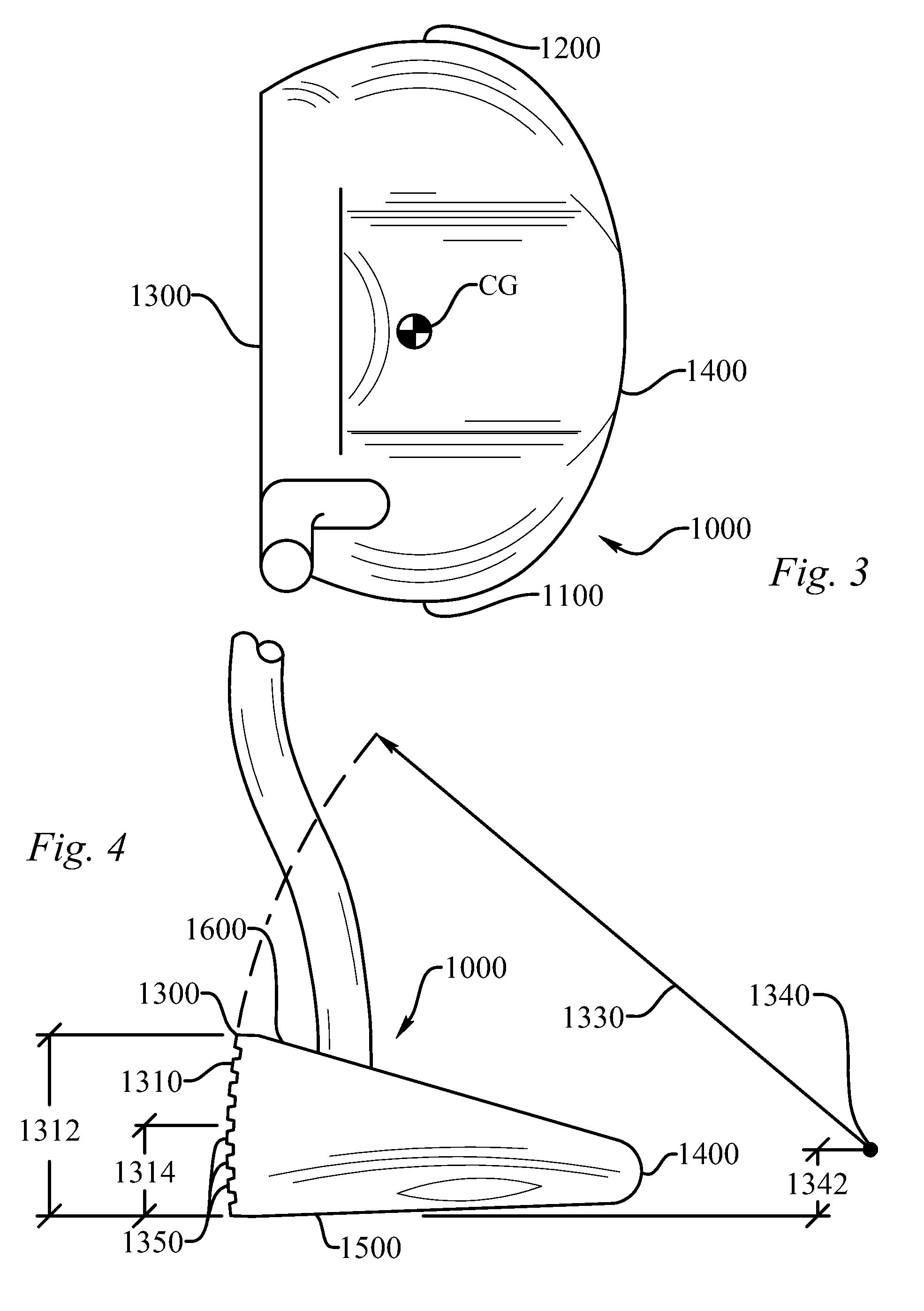
[0005]The ball contact portion includes a plurality of horizontal contact facets, wherein each contact facet has a facet width and a facet length. Each contact facet is vertically curved to match the vertical radius of curvature. The horizontal contact facets, along with many other factors including, but not limited to, the radius of curvature, ensures that no more than two of the plurality of horizontal contact facets contact the golf ball when struck by the ball contact portion at a putter head speed of less than 15 miles per hour. This produces a horizontal linear contact, or impact, geometry that compensates for misdirection of the path of the putter head throughout the stroke of the putter head.

Problems solved by technology

However, many problems associated with a golfer's putting can be linked to a putting stroke that cuts across the ball, or unnecessarily lofts or delofts the putter face at impact.

Method used


Image

  • Vertically curved face putter with multiple horizontal contact facets
  • Vertically curved face putter with multiple horizontal contact facets
  • Vertically curved face putter with multiple horizontal contact facets

Examples


Embodiment Construction

[0018]All patents, patent applications, government publications, government regulations, and literature references cited in this specification are hereby incorporated herein by reference in their entirety. In case of conflict, the present description, including definitions, will control. Definitions for the following terms are provided to promote a further understanding of the present invention.

[0019]The terms used throughout this document are common in the field of golf putters; however, a few of the terms are expressly defined. The term “contact area” as used herein refers to the area on either a putter face striking area or a golf ball where there is contact between the ball and the putter blade. The term “proximal” as used herein refers to the direction or portion of a putter near to the golfer when in use. The term “distal” as used herein refers to the direction or portion of a putter away from the golfer when in use. The term “front” as used herein refers to the edge of the pu...


PUM


Abstract

A golf putter head having a vertically curved putter face with multiple horizontal contact facets. The face has a vertical radius of curvature that is at least 2 inches and no more than 3.5 inches. The face includes a plurality of horizontal contact facets that are vertically curved to match the vertical radius of curvature. The contact facets, along with the radius of curvature, ensure that no more than two of the horizontal contact facets contact the golf ball when struck by the putter head at a speed of less than 15 miles per hour. The putter produces a horizontal linear contact, or impact, geometry that compensates for misdirection of the path of the putter head throughout the stroke of the putter head. At least one of the horizontal contact facets is located at an elevation above the center of curvature and at least one is located below.

Description

CROSS-REFERENCE TO RELATED APPLICATIONS[0001]This application is a continuation-in-part of U.S. patent application Ser. No. 11 / 764,209, filed on Jun. 17, 2007 now abandoned which is a Divisional of U.S. patent application Ser. No. 11 / 408,830 filed on Apr. 21, 2006 now abandoned, which was a Continuation-in-part of U.S. patent application Ser. No. 11 / 173,066 filed on Jul. 1, 2005 now abandoned, which was a Continuation-in-part of U.S. patent application Ser. No. 10 / 672,185, filed on Sep. 26, 2003 now U.S. Pat. No. 6,962,537; all of which are incorporated by reference as if completely written herein.STATEMENT REGARDING FEDERALLY SPONSORED RESEARCH OR DEVELOPMENT[0002]Not ApplicableBACKGROUND OF THE INVENTION[0003]Golf putter designs often focus on proper alignment and minimizing the effects of off-center hits toward the toe or heel. However, many problems associated with a golfer's putting can be linked to a putting stroke that cuts across the ball, or unnecessarily lofts or delofts t...

Claims


Application Information

Patent Timeline
Patent Type & Authority Patents(United States)
IPC IPC(8): A63B53/04
CPCA63B53/0487A63B2053/0408A63B2053/0441A63B2053/0433A63B2053/0445A63B2053/0416A63B53/0408A63B53/0416A63B53/0433A63B53/0441A63B53/0445
Inventor JOHNSON, LANNY L.
Owner JOHNSON LANNY L
Learn More