
Magnetic wellbore cleaning tool

a cleaning tool and wellbore technology, applied in the field of wells, can solve the problems of shortening wasting a portion of the attractive force of the magnet, and other types of magnetic cleaning tools have a limited amount of collection space, so as to shorten the life of the tool, and reduce the cost of the tool

Inactive Publication Date: 2010-07-13
WELLBORE SPECIALTIES
View PDF22 Cites 15 Cited by
  • Summary
  • Abstract
  • Description
  • Claims
  • Application Information

AI Technical Summary

Benefits of technology

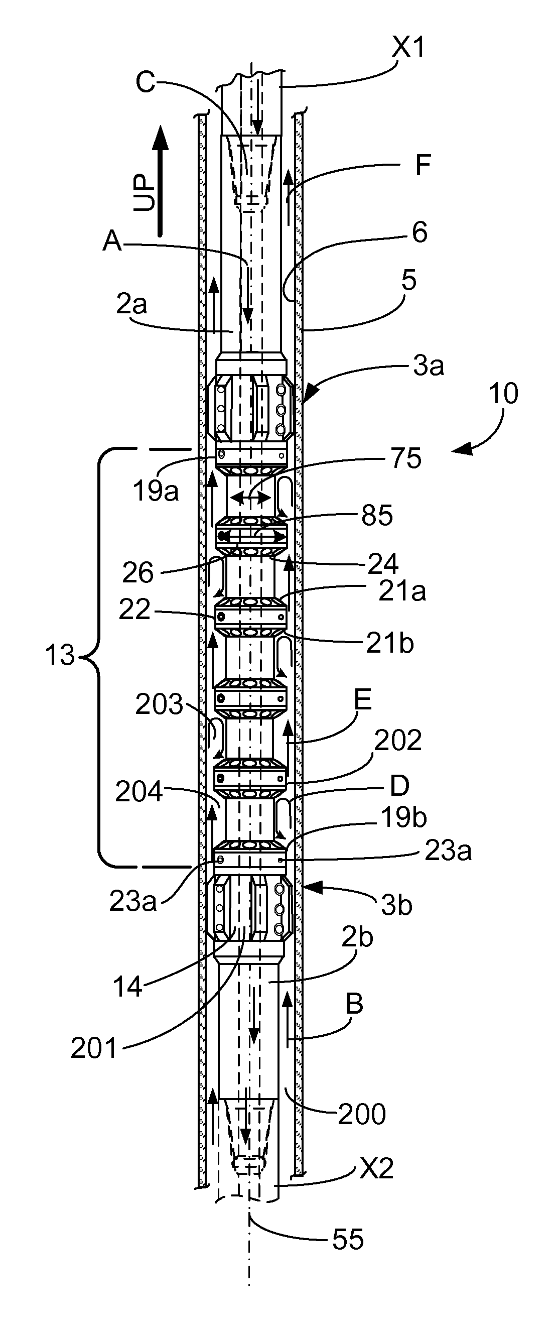
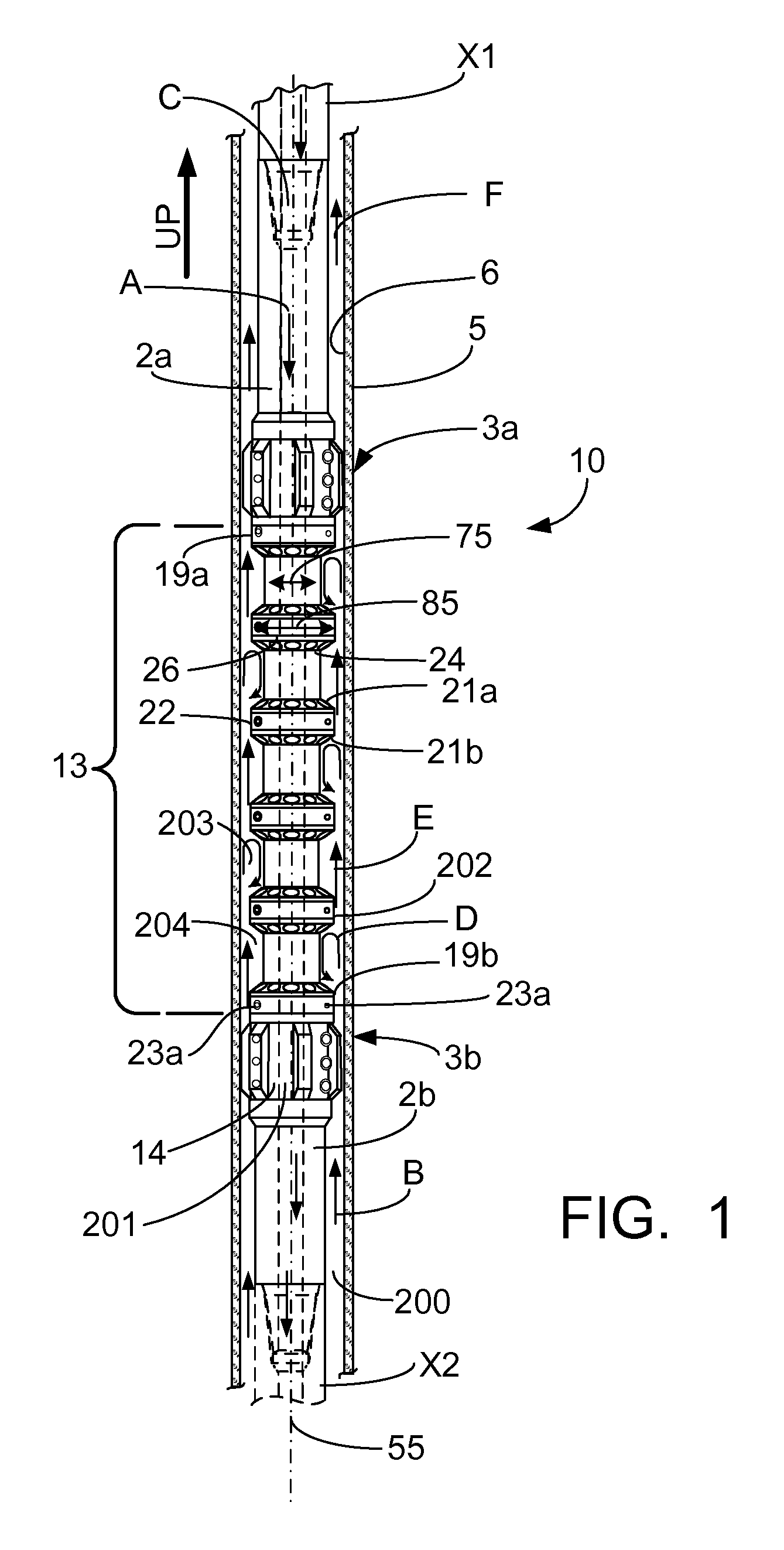
[0006]Thus, it is an object of the present invention to create a simple, strong magnetic cleaning tool with maximized collection area. It is a further object of the present invention to create a more effective ferromagnetic debris collection tool by repeatedly changing the velocity of passing circulating fluid so that the ferromagnetic particles suspended in said fluid are, I speculate, caught in turbulent eddies which I further speculate keep said particles within the tool's magnetic field for a longer period of time and consequently, I further speculate, facilitating more effective collection by the present invention via magnetic attractive force.
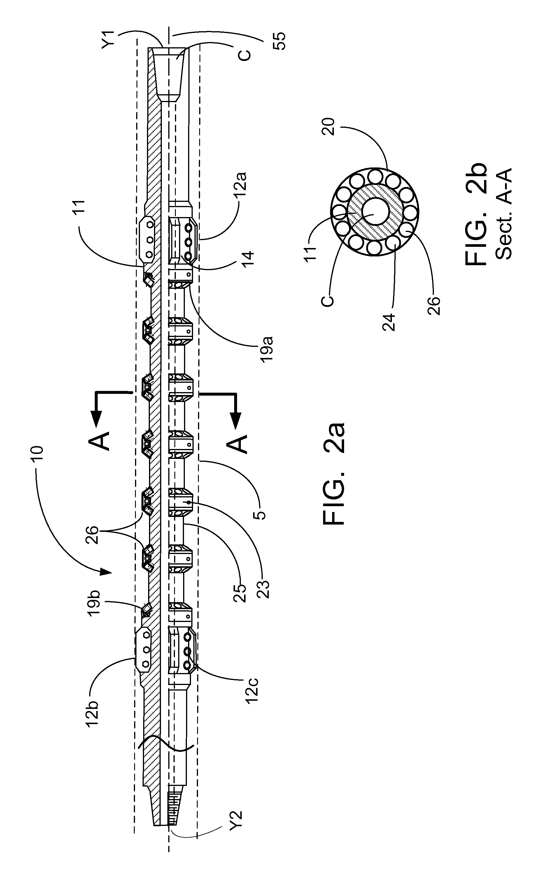
[0011]In either disclosed embodiment of the present invention, adjacent magnetic ridges are separated by a circumferential secondary collection area wherein I speculate that ferromagnetic debris is collected due to the magnetic force created by the magnets held in the magnetic ridges. The tool diameter is smaller in the secondary collection areas than it is at the magnetic ridges; therefore, the annulus between the tool body and the wellbore casing is correspondingly larger. I speculate that this change in the size of the annulus will reduce the velocity of passing fluid, thereby creating eddy currents that will keep ferromagnetic debris that is suspended in the fluid within range of the magnetic attractive force of the present invention. I further speculate that this increased exposure to the magnetic attractive force of the present invention will enable the present invention to more effectively collect ferromagnetic debris suspended in passing circulating fluids.

Problems solved by technology

Other types of magnetic cleaning tools have a limited amount of collection space.
Still others utilize only one pole of the magnets included in the tool, thereby potentially wasting a portion of the magnets' attractive force.
Yet others involve slots or recesses in the tool body itself, thereby, I speculate, exposing the tool to stress points that can shorten the life of the tool and potentially lead to a break occurring during cleaning operations.

Method used


Image

  • Magnetic wellbore cleaning tool
  • Magnetic wellbore cleaning tool
  • Magnetic wellbore cleaning tool

Examples


second embodiment

[0042]A second exemplary embodiment of the present invention is shown in FIGS. 5a-9. This second embodiment is generally referred to as numeral 100. The magnetic wellbore cleaning tool 100 generally comprises a tool body 111 including top tool joint 102a for connection with an upper tubing string X10 and bottom tool joint 102b for connection with lower tubing string X20, top and bottom slotted centralizers 112a and 112b secured around the circumference of said tool joints 102a and 102b and configured to centralize the tool body 111 in the wellbore casing 105, and a central tool body portion 130 found between the top and bottom tool joints 102a and 102b.

[0043]The tool body 111 is a single-piece, unitary machined structure. The tool body 111 has a top tool joint 102a and a bottom tool joint 102b for coupling the tool 100 to upper and lower tubing strings X10 and X20, respectively. The top and bottom tool joints 102a and 102b are shown as threaded. Thus, tool 100 may be directly conne...


PUM


Abstract

A magnetic wellbore cleaning tool having a plurality of magnetic ridges spaced longitudinally between top and bottom centralizers. In operation, the magnetic ridges modify the velocity of passing fluid circulating in the wellbore such that the fluid remains in close proximity to the tool's magnetic field thereby allowing for collection of ferromagnetic debris suspended in cleaning fluid circulating in a wellbore.

Description

BACKGROUND OF THE INVENTION[0001]I. Field[0002]The present invention relates to wells for producing gas and oil and, more particularly, to wellbore cleaning tools, and more particularly, to magnetic wellbore cleaning tools which collect ferromagnetic materials suspended in wellbore fluid.[0003]II. Background[0004]Various drilling and cleaning operations in the oil and gas industry create debris that becomes trapped in a wellbore, including ferromagnetic debris. Generally, fluids are circulated in such a wellbore to washout debris before completion of the well. Several tools have been developed for the removal of ferromagnetic debris from a wellbore. There is a continuing need for a more effective magnetic wellbore cleaning tool.BRIEF SUMMARY OF THE INVENTION[0005]Other types of magnetic cleaning tools have a limited amount of collection space. Still others utilize only one pole of the magnets included in the tool, thereby potentially wasting a portion of the magnets' attractive forc...

Claims


Application Information

Patent Timeline
Patent Type & Authority Patents(United States)
IPC IPC(8): E21B31/06
CPCE21B37/00
Inventor PENISSON, DENNIS J.
Owner WELLBORE SPECIALTIES
Learn More