Supercharge Your Innovation With Domain-Expert AI Agents!

Composite screen

a technology of composite screen and oilfield shaker, which is applied in the direction of screening, solid separation, chemistry apparatus and processes, etc., can solve the problems of time-consuming and expensive mud evaluation and mixture process, too light may not protect, and too heavy may over-invade the formation

Inactive Publication Date: 2010-07-13
MI
View PDF26 Cites 3 Cited by
  • Summary
  • Abstract
  • Description
  • Claims
  • Application Information

AI Technical Summary

Benefits of technology

The present invention relates to a screen frame for a shale shaker, which includes a first end, a second end, a first side, and a second side. The screen frame also includes a plurality of transverse ribs disposed between the first side and the second side, with at least one transverse rib extending downwardly below the lower plane of the screen frame. Additionally, the screen frame may also include a gasket integrally molded with the frame or a positioning tab. The technical effects of this invention include improved screening efficiency, reduced wear and tear, and increased durability of the screen frame.

Problems solved by technology

Drilling mud that is too light may not protect the formation from blow outs, and drilling mud that is too heavy may over invade the formation.
Because the mud evaluation and mixture process is time consuming and expensive, drillers and service companies prefer to reclaim the returned drilling mud and recycle it for continued use.
Further, disposal of drilling mud may present an environmental hazard.
Often, the filter screens of shale shakers, through which the solids are separated from the drilling mud, wear out over time and need replacement.
The frame of the vibrating screen is resiliently suspended or mounted upon a support and is caused to vibrate by a vibrating mechanism, e.g. an unbalanced weight on a rotating shaft connected to the frame.
The displaced shaker screen 2 may result in poor sealing between the shaker screen 2 and a sealing surface of the shale shaker 20.
However, friction between a rubber seal or gasket disposed on the sealing surface of the shaker screen 2 inhibits moving the screen 2 into position.
Additionally, it is common for the pin to tear or damage the gasket, thereby reducing efficiency of the seal.

Method used


Image

  • Composite screen
  • Composite screen
  • Composite screen

Examples


Embodiment Construction

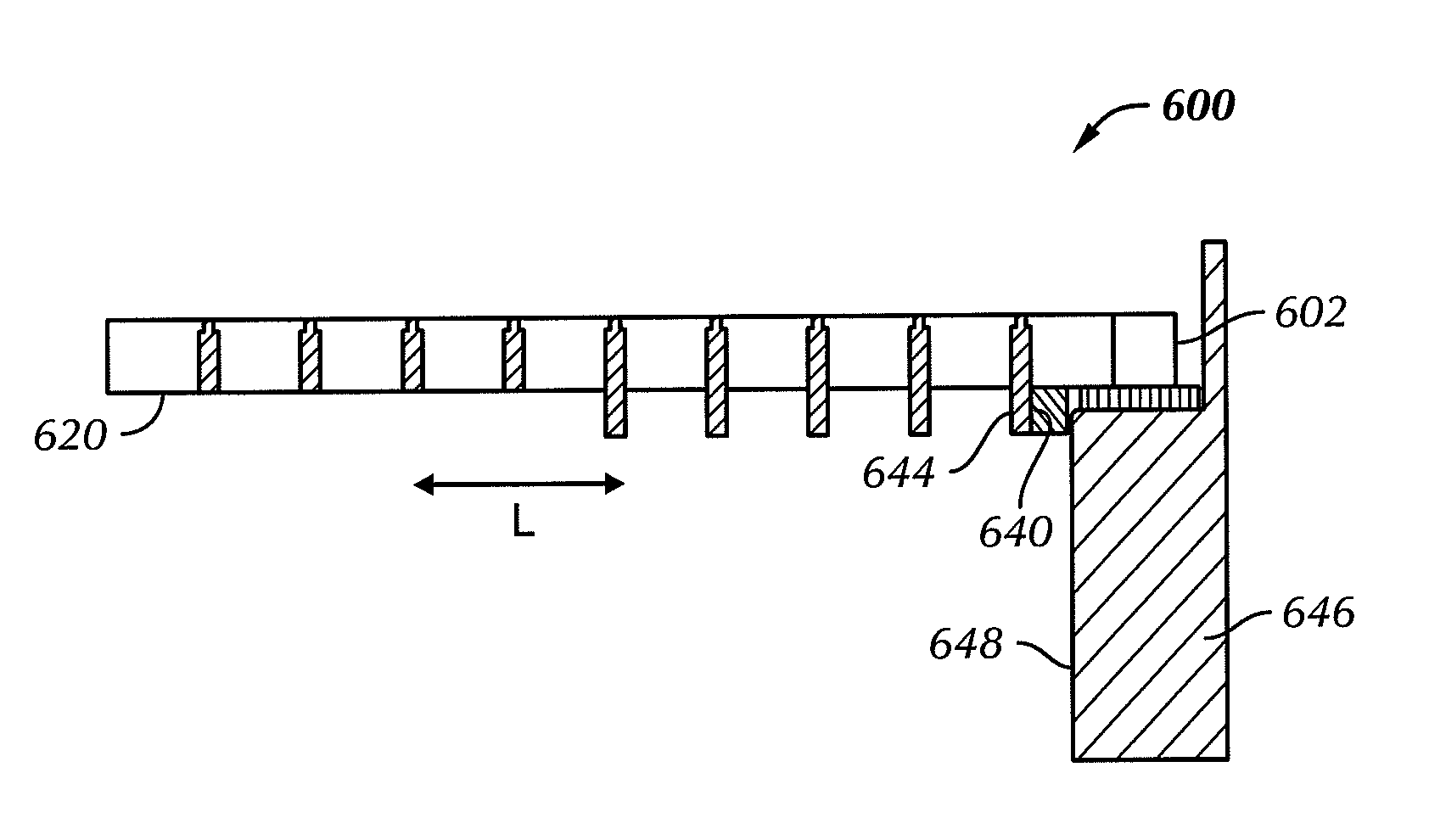
[0028]In one aspect, embodiments disclosed herein relate to a screen frame for an oilfield shale shaker. Specifically, embodiments disclosed herein relate to a screen frame that may provide more efficient sealing of a screen frame within a shale shaker. Additionally, embodiments disclosed here relate to a screen frame that may limit or reduce displacement of a screen frame during installation of the screen frame. Further, embodiments disclosed herein relate to a method of forming a screen frame.

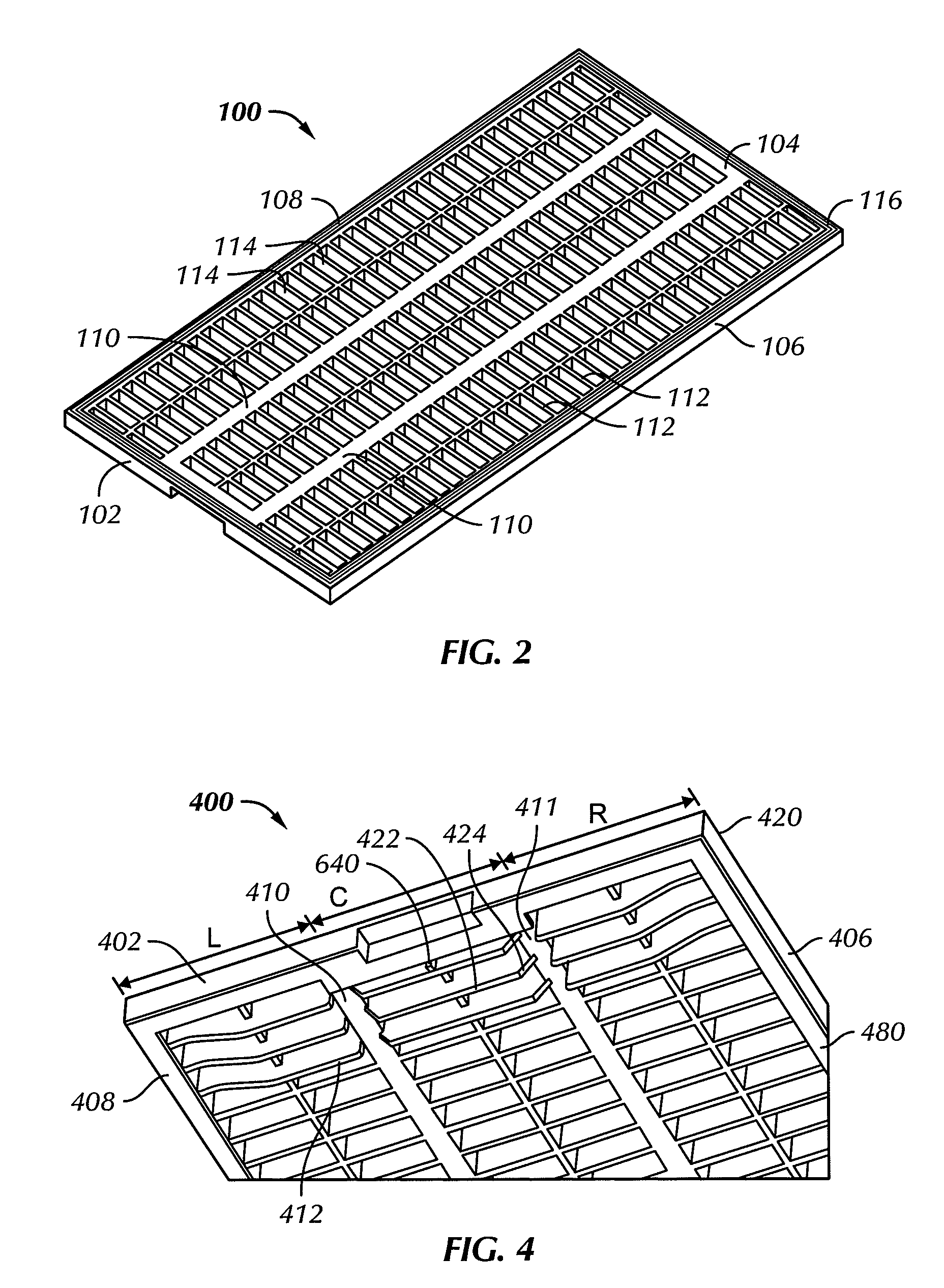
[0029]Referring initially to FIG. 2, a screen frame 100 for an oilfield shaker in accordance with an embodiment of the present invention is shown. The screen frame 100 has a first side 106 and a second side 108 extending between a first end 102 and a second end 104. At least one longitudinal cross-member 110 may extend between first end 102 and second end 104, disposed between first side 106 and second side 108. A plurality of transverse ribs 112 is arrayed between first end 102 and second en...


PUM


Abstract

A screen support frame for a shale shaker includes a first end, a second end disposed opposite the first end, a first side disposed substantially perpendicular the first and second ends, a second side disposed opposite the first side and a plurality of transverse ribs disposed between the first end and the second end and between the first side and the second side, wherein at least one transverse rib extends downwardly below a lower plane of the screen support frame. A method of forming a screen support frame for a shale shaker includes forming a screen support frame and forming integrally a gasket along a perimeter of a lower plane of the screen support frame.

Description

CROSS-REFERENCE TO RELATED APPLICATIONS[0001]This application, pursuant to 35 U.S.C. § 119(e), claims priority to U.S. Provisional Application Ser. No. 60 / 787,277, filed Mar. 30, 2006. That application is incorporated by reference in its entirety.BACKGROUND OF INVENTION[0002]1. Field of the Invention[0003]The invention relates generally to oilfield shale shakers. More particularly, the present invention relates to screen frames for oilfield shale shakers.[0004]2. Background Art[0005]Oilfield drilling fluid, often called “mud,” serves multiple purposes in the industry. Among its many functions, the drilling mud acts as a lubricant to cool rotary drill bits and facilitate faster cutting rates. Typically, the mud is mixed at the surface and pumped downhole at high pressure to the drill bit through a bore of the drillstring. Once the mud reaches the drill bit, it exits through various nozzles and ports where it lubricates and cools the drill bit. After exiting through the nozzles, the “...

Claims


Application Information

Patent Timeline
Patent Type & Authority Patents(United States)
IPC IPC(8): B07B1/49
CPCB07B1/469B07B1/46B07B2201/02
Inventor NOGALSKI, JAMES F.
Owner MI
Features
  • R&D
  • Intellectual Property
  • Life Sciences
  • Materials
  • Tech Scout
  • Unparalleled Data Quality
  • Higher Quality Content
  • 60% Fewer Hallucinations
Learn More