Steering mechanism and method for a manually powered vehicle

a driving mechanism and manual technology, applied in the direction of steering devices, frictional rollers based transmissions, cycle equipments, etc., can solve the problems of not being able to move people, bicycles do not provide a good total body workout, and do not use the upper body muscles of people equally, so as to achieve a simple and cost-effective driving mechanism

Inactive Publication Date: 2010-07-13
MORSE CYCLE
View PDF54 Cites 14 Cited by
  • Summary
  • Abstract
  • Description
  • Claims
  • Application Information

AI Technical Summary

Benefits of technology

[0023]Accordingly, it is an advantage of the present invention to provide a total body workout driving mechanism and a moveable vehicle embodying same.
[0024]It is another advantage of the present invention to provide a rowing vehicle having a simplistic driving mechanism.
[0025]It is a further advantage of the present invention to provide a rowing vehicle having a cost effective driving mechanism.
[0026]It is still another advantage of the present invention to provide a driving mechanism for a two-wheeled rowing vehicle.
[0027]It is still a further advantage of the present invention to provide a driving mechanism for a three-wheeled rowing vehicle.
[0028]It is yet another advantage of the present invention to provide a driving mechanism for a four-wheeled rowing vehicle.

Problems solved by technology

Bicycles, however, do not equally use a person's upper body muscles.
Consequently, bicycles do not provide a good total body workout.
Although rowing machines provide excellent exercise for many muscles including legs, arms, back, shoulders and stomach, they are purely for the benefit of exercise and do not have the ability to move people.
While these machines exist, they have to date not gained widespread commercial popularity.
First, many of the existing rowbikes appear to be awkward and fragile.
Second, the mechanisms that drive the rowbikes appear to be complicated.
That is, when compared to a bicycle, the rowbike designs contain many more parts, which are awkwardly configured.
The numerous and intricately juxtaposed parts create cost and add to the potential for mechanical failure.

Method used


Image

  • Steering mechanism and method for a manually powered vehicle
  • Steering mechanism and method for a manually powered vehicle
  • Steering mechanism and method for a manually powered vehicle

Examples


Embodiment Construction

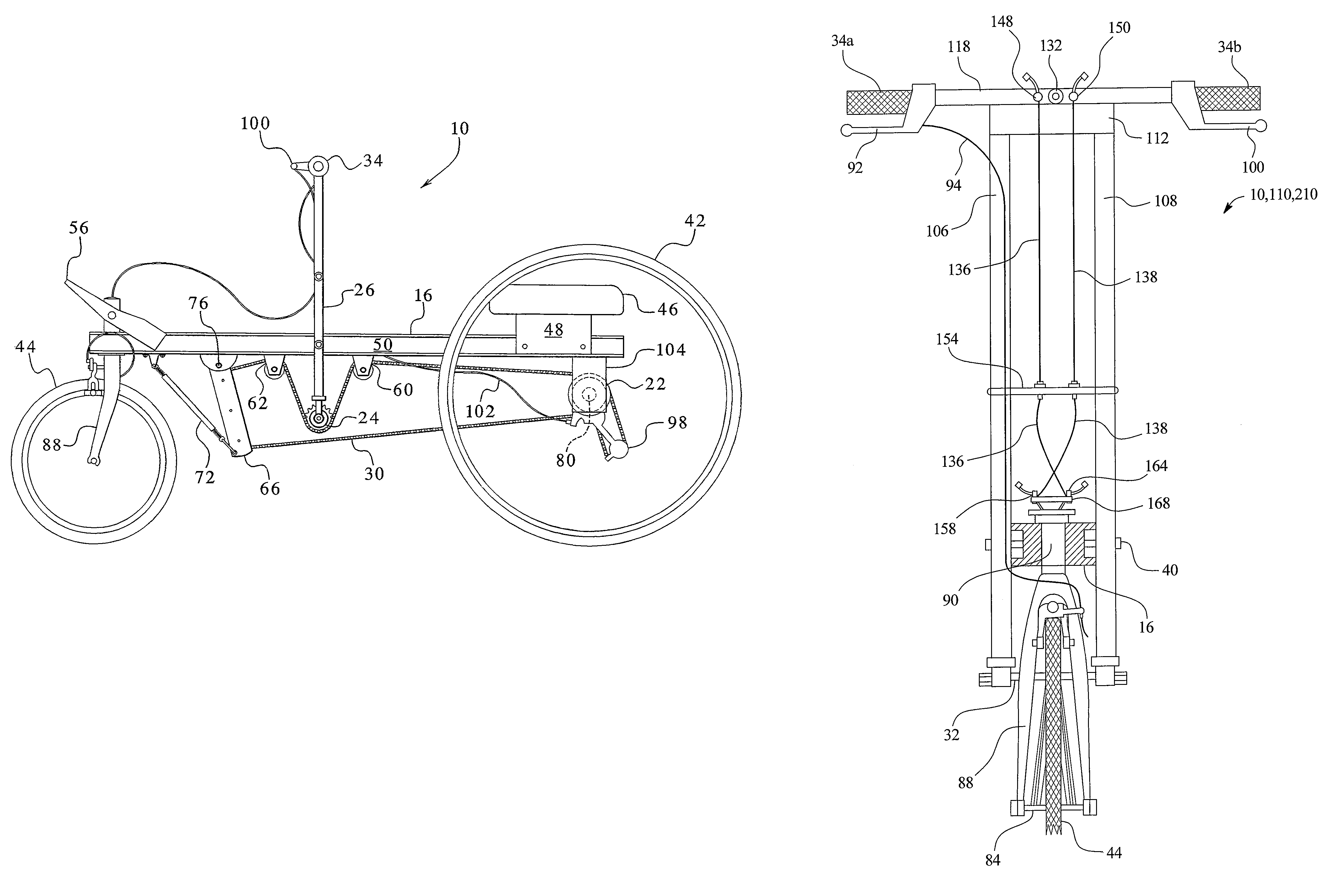
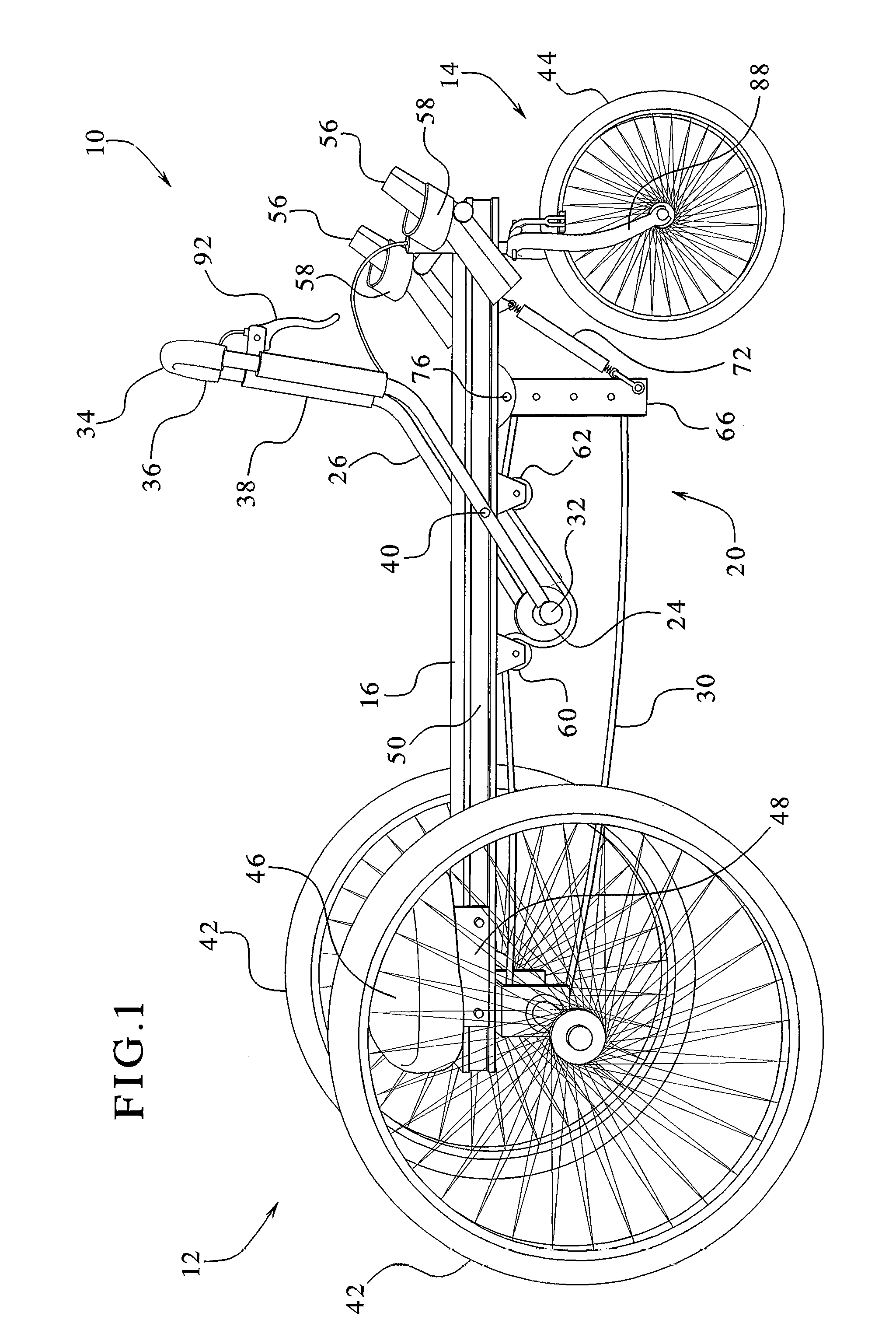
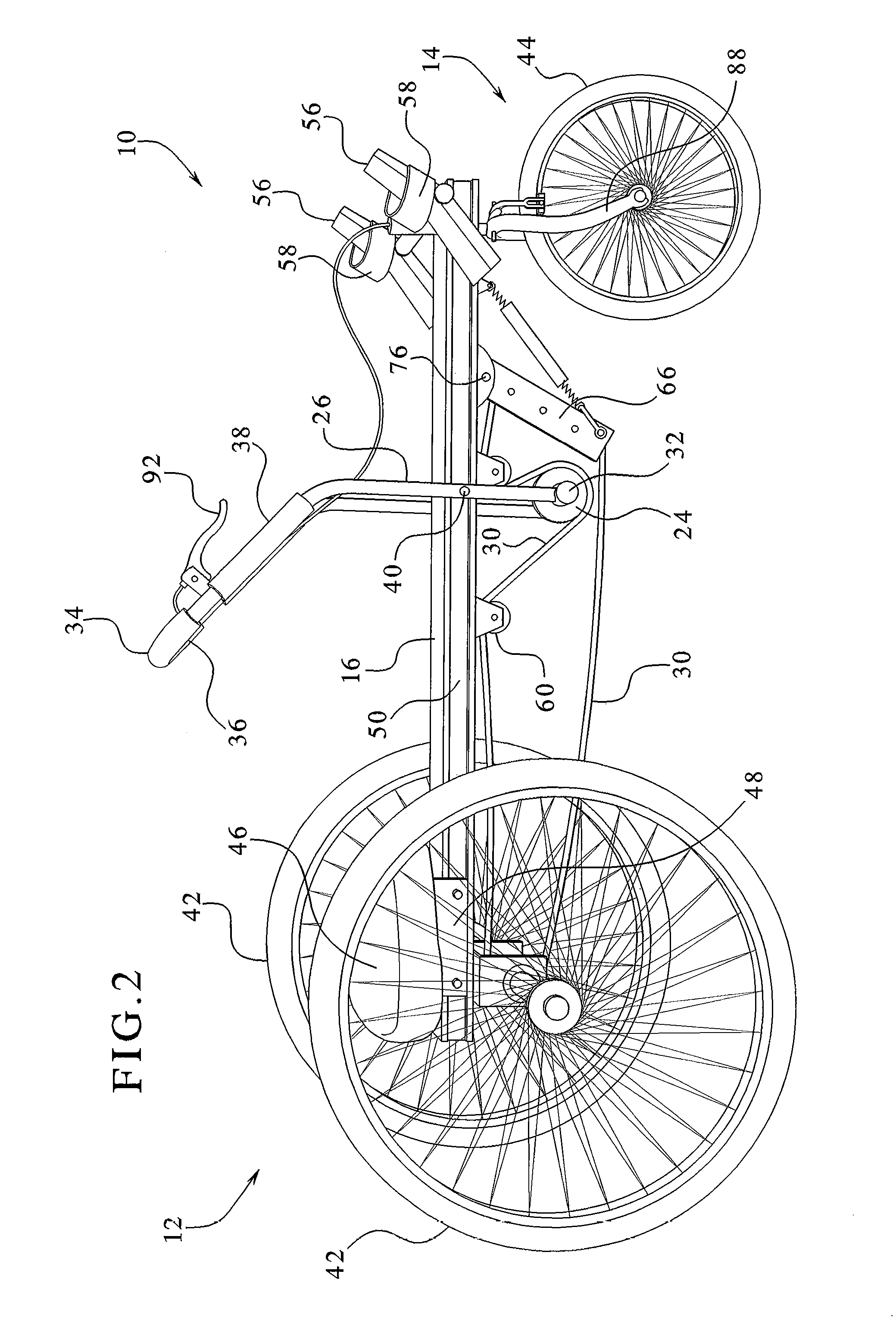
[0048]Referring now to the drawings and in particular to FIG. 1, one embodiment of a row vehicle 10 is illustrated. The row vehicle 10 includes a rear end 12 and a front end 14. A frame 16 is provided. While frame 16 is illustrated herein a simple channel or bar, the frame 16 alternatively has supports or struts commonly provided on bicycles, or other desired structural members, etc. The frame 16 includes flanges and / or channels in order to provide additional strength and also to provide areas on which to mount various items. The frame 16 includes various types of coatings which protect the material of the frame 16 and also provide aesthetic value. For example, if the frame 16 is aluminum, it can be anodized or painted. If steel, frame 16 can be primed and / or bead-blasted and painted or otherwise treated, such as with a plating technique. While a metal or metal alloy frame is preferred, it is also possible that frame 16 is made of plastic, wood, or other suitable material or any com...


PUM


Abstract

A steering mechanism and method for a manually powered vehicle are provided. The steering mechanism includes a stem. An inner shaft freely rotates within the stem. A first end of a first cable and a first end of a second cable are operatively connected to the inner shaft. A second end of the first cable and a second end of the second cable are operatively connected to a steering column. The steering column supports a wheel of the manually powered vehicle. The steering column and the wheel rotate in response to rotation of the steering bar.

Description

PRIORITY CLAIM[0001]This application claims the benefit as a continuation-in-part of U.S. patent application Ser. No. 10 / 884,499, filed Jul. 2, 2004, entitled “Manually Powered Vehicle Having Improved Steering,” which is a continuation-in-part of U.S. patent application Ser. No. 10 / 103,366, filed Mar. 20, 2002, entitled “Manually Powered Drive Mechanism And Vehicle Employing Same,” the entire contents of which are hereby incorporated by reference and relied upon.BACKGROUND OF THE INVENTION[0002]The present invention relates to manually powered vehicles. More particularly, the present invention relates to a manually powered drive mechanism and a vehicle and method of operating a vehicle employing same.[0003]Unicycles, bicycles and tricycles have been used for years to provide an economic mode of transportation, for fun and entertainment, etc. Bicycles are by far the most common of these devices and generally employ power from a person's lower body, wherein foot pedals typically conne...

Claims


Application Information

Patent Timeline
Patent Type & Authority Patents(United States)
IPC IPC(8): B62M1/14
CPCB62K3/005B62K5/00B62M1/14B62M1/16
Inventor DRYMALSKI, ROBERT
Owner MORSE CYCLE
Why Eureka
Try Eureka