Tilt table

a tilt table and table technology, applied in the direction of mechanical control devices, process and machine control, using mechanical means, etc., can solve the problems of inaccurate tilt table and industry limitations in the precision of parts being machined

Active Publication Date: 2010-07-13
PAARADYNE TECH
View PDF22 Cites 19 Cited by
  • Summary
  • Abstract
  • Description
  • Claims
  • Application Information

AI Technical Summary

Problems solved by technology

The industry has been somewhat limited in the precision of the part being machined due to the lack of stability of the current tilt tables from movement during the machining of a part.
Duri...

Method used


Image

  • Tilt table
  • Tilt table
  • Tilt table

Examples


Embodiment Construction

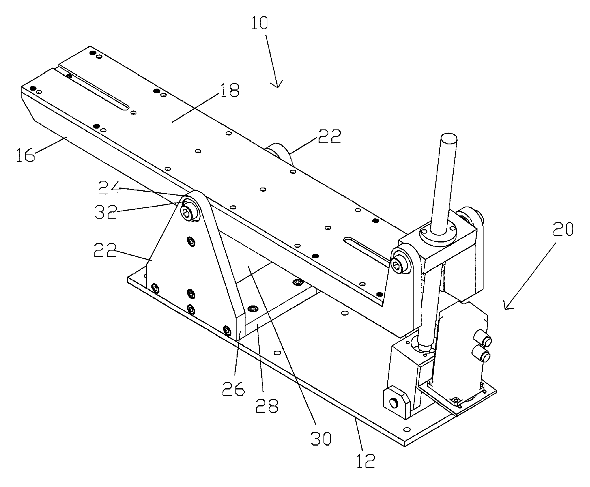
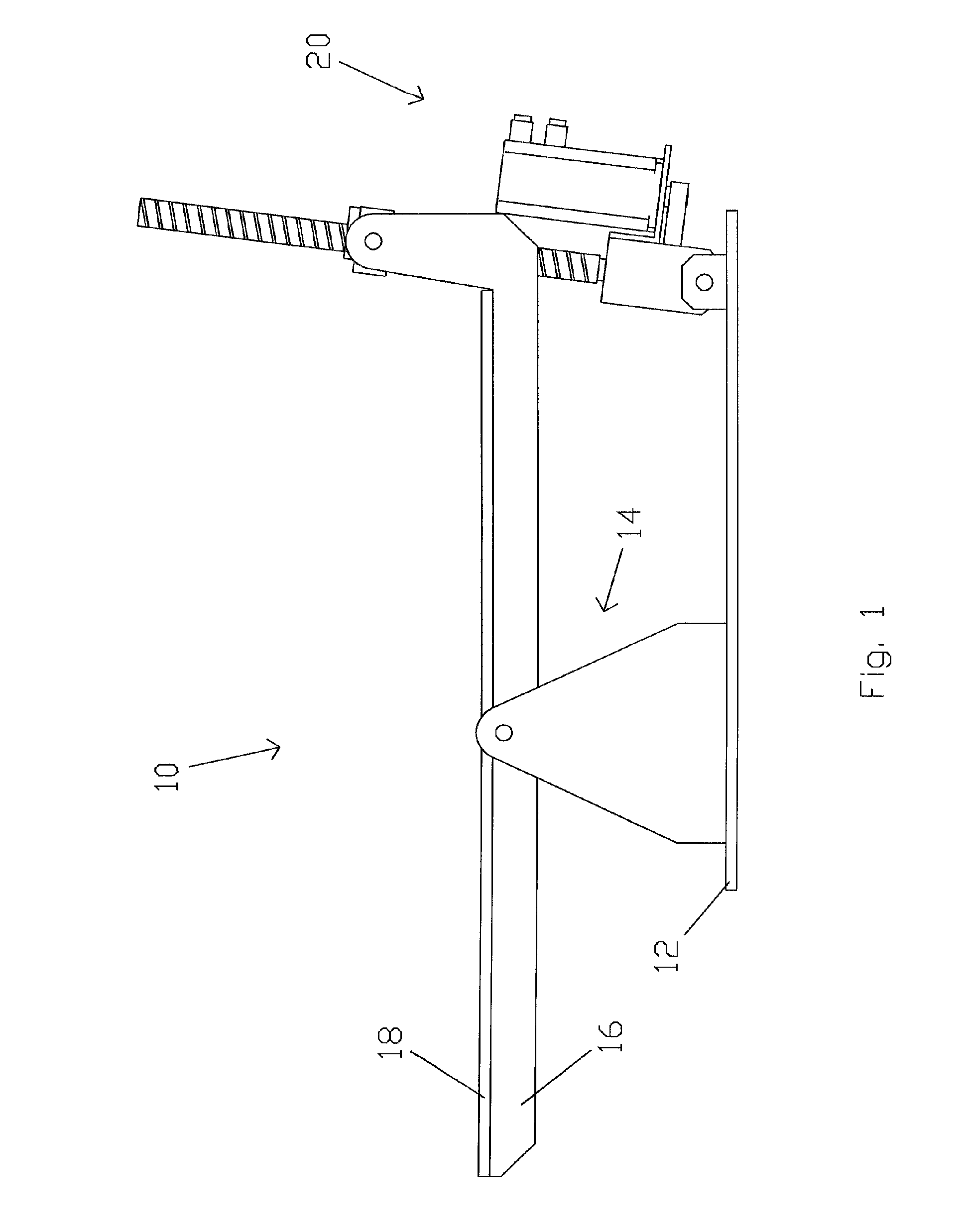
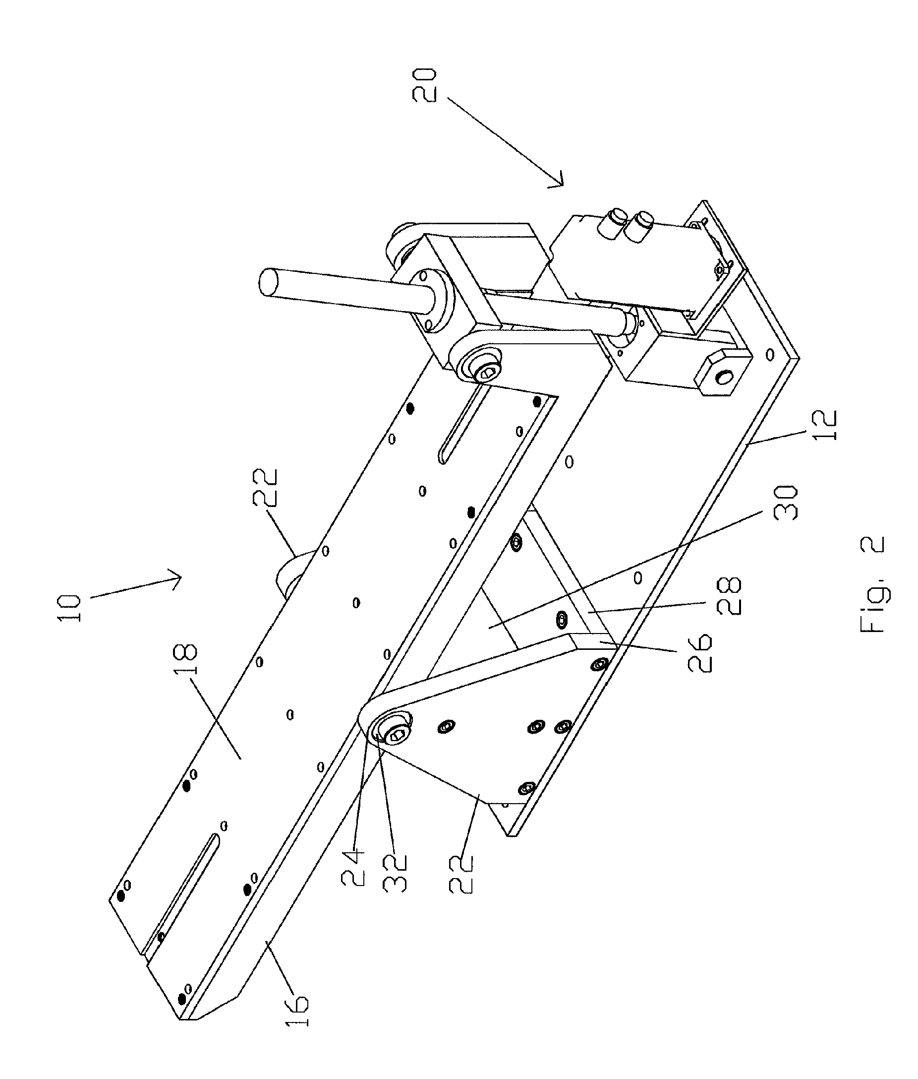
[0018]The present invention is a tilt table 10, as shown in FIGS. 1-11. The tilt table 10 includes a main mounting plate 12, pivot assembly 14, table support beams 16, table top 18 and movement assembly 20. The main mounting plate 12 is used to mount the tilt table 10 to a milling machine. The other components of the tilt table 10 are mounted to the main mounting plate 12. The pivot assembly 14 includes two pivot supports 22 having a top 24 and a bottom 26. A horizontal cross brace 28 and vertical cross brace 30 are secured between the pivot supports 22. The horizontal cross brace 28 is mounted to the main mounting plate 12 and to the bottom of each pivot support 22. The vertical cross brace 30 is mounted along the each pivot support 22 between the top 24 and bottom 26 of each pivot support 22. Together, the horizontal cross brace 28 and vertical cross brace 30 are used to provide strength and support for the pivot supports 22 and to mount the pivot supports 22 to the main mounting ...


PUM


Abstract

A tilt table for use with a milling machine. The tilt table includes at least one pivot support attachable to the milling machine. The tilt table includes a table top pivotally attached to the at least one pivot support. The table top has two ends. The tilt table includes at least one movement assembly attached to at least one end of the table top to move the table top about the at least one pivot support.

Description

[0001]This application claims the benefit of U.S. Provisional Application No. 60 / 522,230, filed Sep. 3, 2004.BACKGROUND[0002]The present invention generally relates to computer controlled machining on computer controlled milling machines. More specifically, the present invention relates to tilt tables used in the machining of parts on computer controlled milling machines.[0003]The use of tilt tables in the machining of parts is not new to the industry. Tilt tables allow mill operators to produce parts of greater complexity. Tilt tables allow the addition of a fourth and fifth axis capability to machine tools that only support three axes of motion. Tilt tables may be combined with other fixtures such as a rotary table to produce complex parts with relative ease. The current state of the art of tilt tables places an angle control device, usually a worm and ring gear actuated by a servo motor, at the center or pivot axis of the tilt table. The industry has been somewhat limited in the ...

Claims


Application Information

Patent Timeline
IPC IPC(8): B23C1/14
CPCB23Q1/52B23Q5/40Y10T409/30896Y10T74/20341Y10T408/5614Y10T409/305824
Inventor MCCULLOCH, JOSEPH W.
Owner PAARADYNE TECH
Why Eureka
Try Eureka