

Flow control device utilizing a reactive media
a technology of reactive media and flow control device, which is applied in the direction of fluid removal, borehole/well accessories, construction, etc., can solve the problems of unsatisfactory conditions and reduce the amount and quality of produced oil
- Summary
- Abstract
- Description
- Claims
- Application Information
AI Technical Summary
Benefits of technology
Problems solved by technology
Method used
Image

Examples
Embodiment Construction
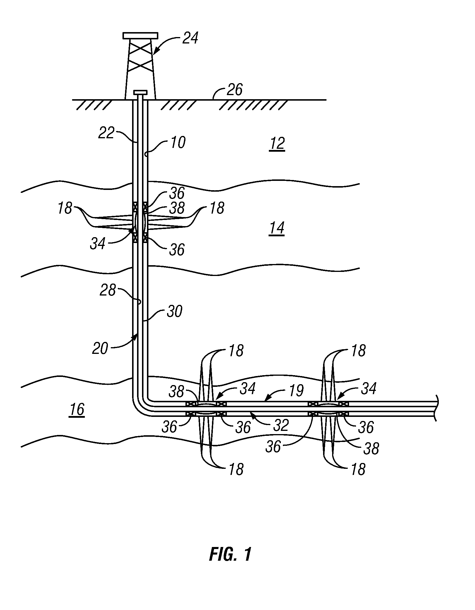
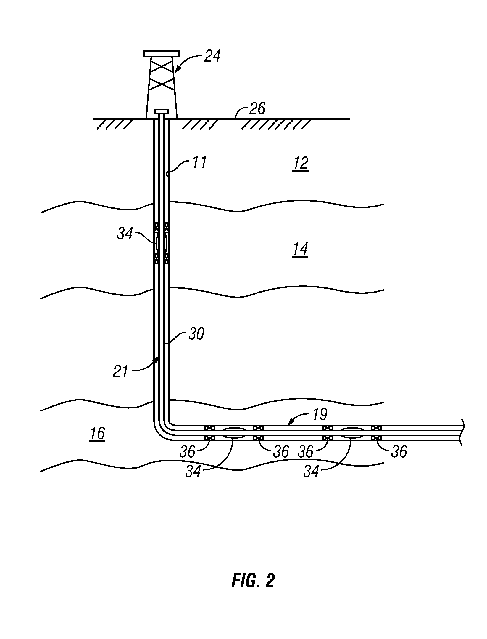
[0021]The present disclosure relates to devices and methods for controlling production of a hydrocarbon producing well. The present disclosure is susceptible to embodiments of different forms. There are shown in the drawings, and herein will be described in detail, specific embodiments of the present disclosure with the understanding that the present disclosure is to be considered an exemplification of the principles of the disclosure, and is not intended to limit the disclosure to that illustrated and described herein. Further, while embodiments may be described as having one or more features or a combination of two or more features, such a feature or a combination of features should not be construed as essential unless expressly stated as essential.
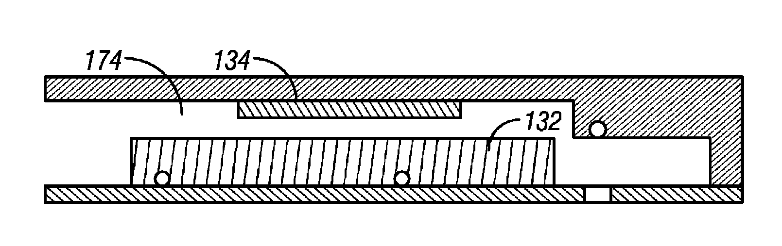
[0022]In one embodiment of the disclosure, in-flow of water into the wellbore tubular of an oil well is controlled, at least in part using an in-flow control element that contains a media that can interact with water in fluids produced ...
PUM
 Abstract
Description
Claims
Application Information