AI technical title is built by Patsnap AI team. It summarizes the technical point description of the patent document.
a technology of energy absorption and energy, applied in the direction of traffic signals, traffic restrictions, ways, etc., can solve the problems of increasing the average speed of trains and vehicles, increasing the number of vehicles, and the inability of vehicles to cross and traditional systems for preventing vehicles from crossing the tracks at the inopportune time have not been fully satisfactory
Active Publication Date: 2010-08-31
GLOBAL GRAB TECH INC
View PDF67 Cites 33 Cited by
Summary
Abstract
Description
Claims
Application Information
AI Technical Summary
This helps you quickly interpret patents by identifying the three key elements:
Problems solved by technology
Method used
Benefits of technology
Problems solved by technology
The problem of vehicles improperly crossing railroad tracks is becoming more pronounced due to a rise in both the average speed of trains and in the number of vehicles on the roads.
Traditional systems for preventing vehicles from crossing the tracks at inopportune times have proved less than fully satisfactory.
Other vehicle barriers have been proposed, but none have solved the problem in a manner that is both feasible and commercially practical.
Method used
Image
Click on the blue label to locate the original text in one second.
Reading with bidirectional positioning of images and text.
Examples
example
[0054]An embodiment similar to that shown in FIGS. 3A and 3B was constructed without ground retractability, as follows. The overall width of the installation was 18.4 m (60.4 ft) centerline to centerline of the stanchions. The net width was 10.5 m (34.5 ft). The uninstalled constructed net height was 0.9 m (3.0 ft). The height of the net when installed and tensioned was 1.0 m (3.3 ft) to the center of the top cable and 0.2 m (0.7 ft) to the center of the bottom cable as measured at the centerline of the net assembly. A measure of the tension was recorded in the top and bottom cables of 27.5 kN (6182.3 lb) and 17.5 kN (3934.2 lb), respectively.
[0055]The cable net was constructed of three equally spaced horizontal members. The top and bottom horizontals were 19 mm (0.8 in) diameter Extra High Strength (EHS) wire strand. The center horizontal was 16 mm diameter 6×26 wire rope. The horseshoe cable net members were fabricated of a single 16 mm (0.6 in) diameter 6×26 wire rope. The wire r...
PUM
Abstract
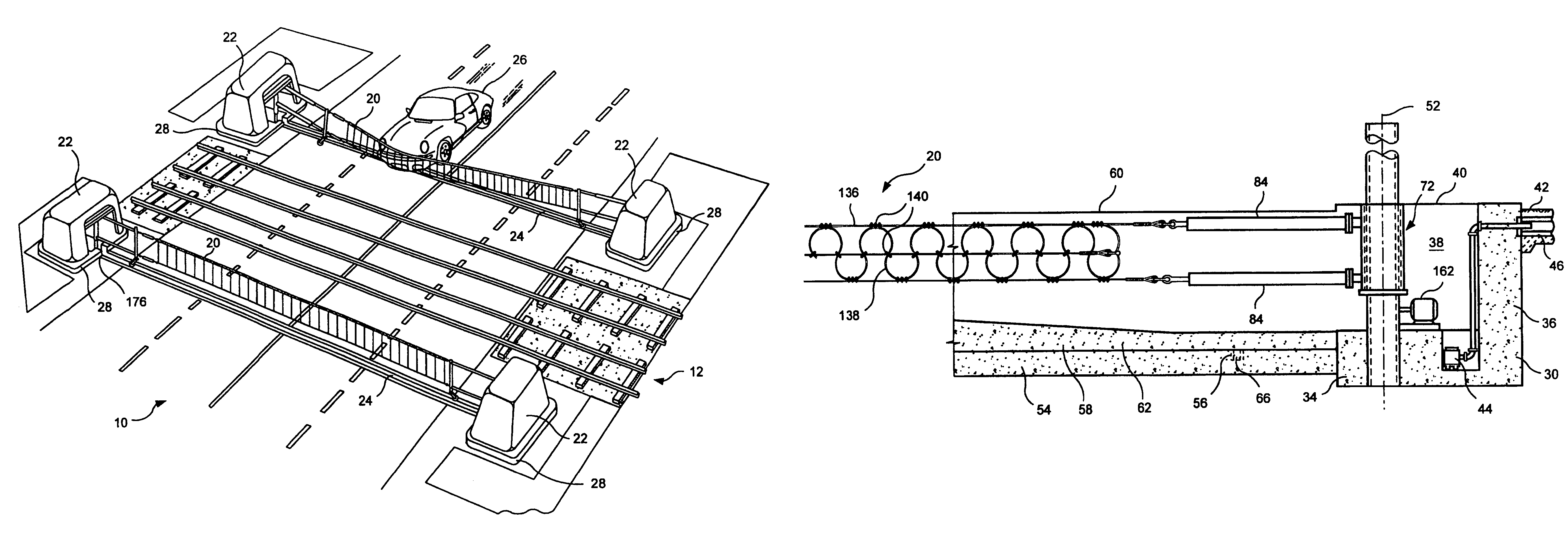
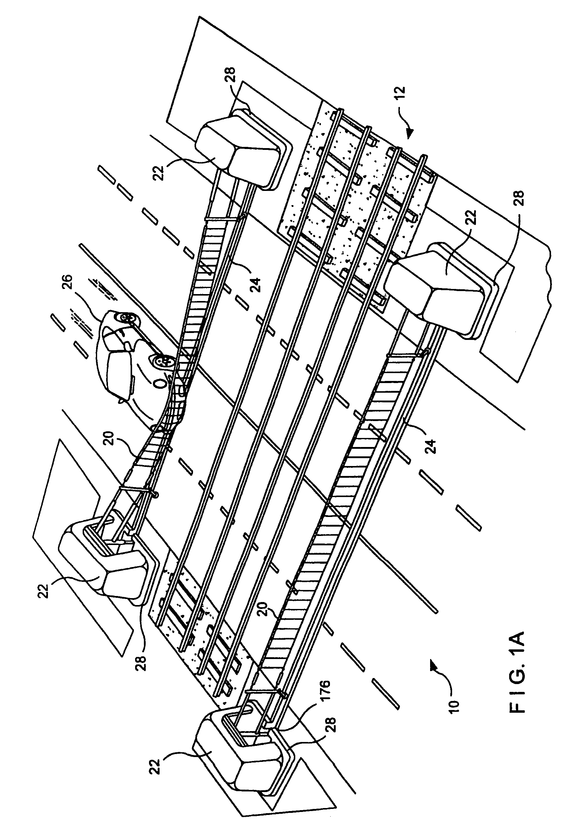
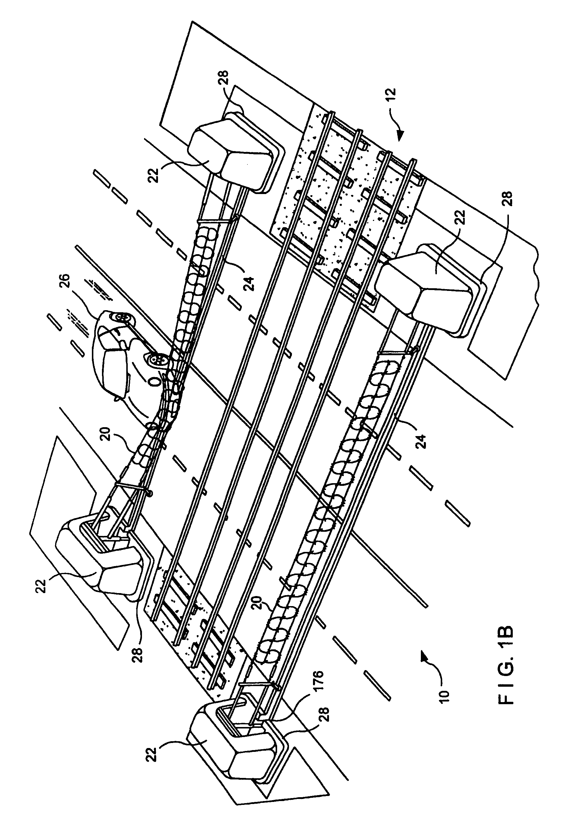
A heavy duty ground retractable automobile barrier for a railroad crossing. Concrete bunkers are placed at each side of a roadway. An upstanding concrete-filled steel pipe fixed in each bunker has a sleeve for rotational and axial movement. Shock absorbers are mounted on each sleeve. A net extends across the road and is attached to the opposite ends of the shock absorbers. Collision of an automobile with the net creates tensile forces in the net. The shock absorbers expand while rotating about the pipe's axis in response to tensile forces from the net that meet or exceed a minimum threshold. Forces from the net pass through the axis of the steel pipe. The net is stored in a pit transverse the roadway parallel to the railroad tracks and is raised and lowered as appropriate. The net includes a cable that extends across the road in a wave pattern, having peaks, valleys and midpoints, wherein tangents of the wave midpoints are at least 90 degrees from tangents of the peaks and valleys.
Description
RELATED APPLICATIONS[0001]This application is the National Stage of International Application No. PCT / US03 / 03586, entitled “Energy Absorbing System” and filed Feb. 6, 2003, which claims priority from Non-provisional application Ser. No. 10 / 359,666, U.S. Pat. No. 6,843,613, entitled “Energy Absorbing System” and filed Feb. 6, 2003, which claims priority from U.S. Provisional Application Ser. No. 60 / 421,144, entitled “Energy Absorbing System”, filed on Feb. 7, 2002, and converted to a provisional application on Feb. 5, 2003. International Application No. PCT / US03 / 03586, also claims priority from U.S. Provisional Application Ser. No. 60 / 421,144, entitled “Energy Absorbing System”, filed on Feb. 7, 2002, and converted to a provisional application on Feb. 5, 2003.BACKGROUND OF THE INVENTION[0002]This invention relates to an energy absorbing system that can be used to dissipate unwanted energy such as, e.g., the energy of an errant vehicle. The system can be used in a variety of applicati...
Claims
Application Information
Patent Timeline
Application Date:The date an application was filed.
Publication Date:The date a patent or application was officially published.
First Publication Date:The earliest publication date of a patent with the same application number.
Issue Date:Publication date of the patent grant document.
PCT Entry Date:The Entry date of PCT National Phase.
Estimated Expiry Date:The statutory expiry date of a patent right according to the Patent Law, and it is the longest term of protection that the patent right can achieve without the termination of the patent right due to other reasons(Term extension factor has been taken into account ).
Invalid Date:Actual expiry date is based on effective date or publication date of legal transaction data of invalid patent.

