
Double mounted dual switch box bracket—stud divider

a dual-switch box, stud-mounted technology, applied in the direction of coupling device connection, curtain suspension device, instruments, etc., can solve the problems of difficult placement of a second box directly on the opposite side of the first box, difficult mounting of the second box bracket, and the second box cannot be easily attached to the stud above, so as to facilitate the bending of the member

Active Publication Date: 2010-09-21
THOMAS & BETTS INT INC
View PDF21 Cites 28 Cited by
  • Summary
  • Abstract
  • Description
  • Claims
  • Application Information

AI Technical Summary

Benefits of technology

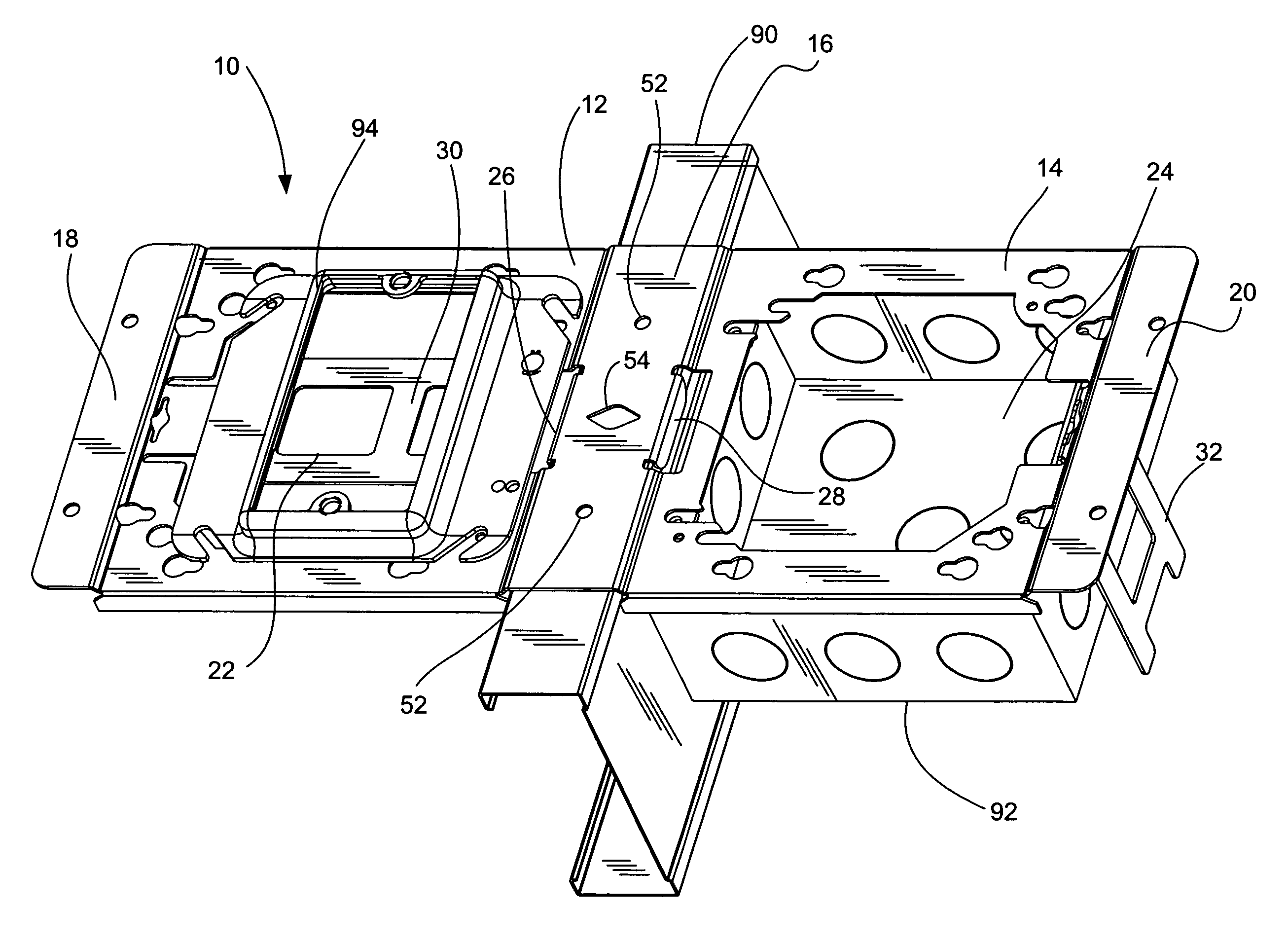
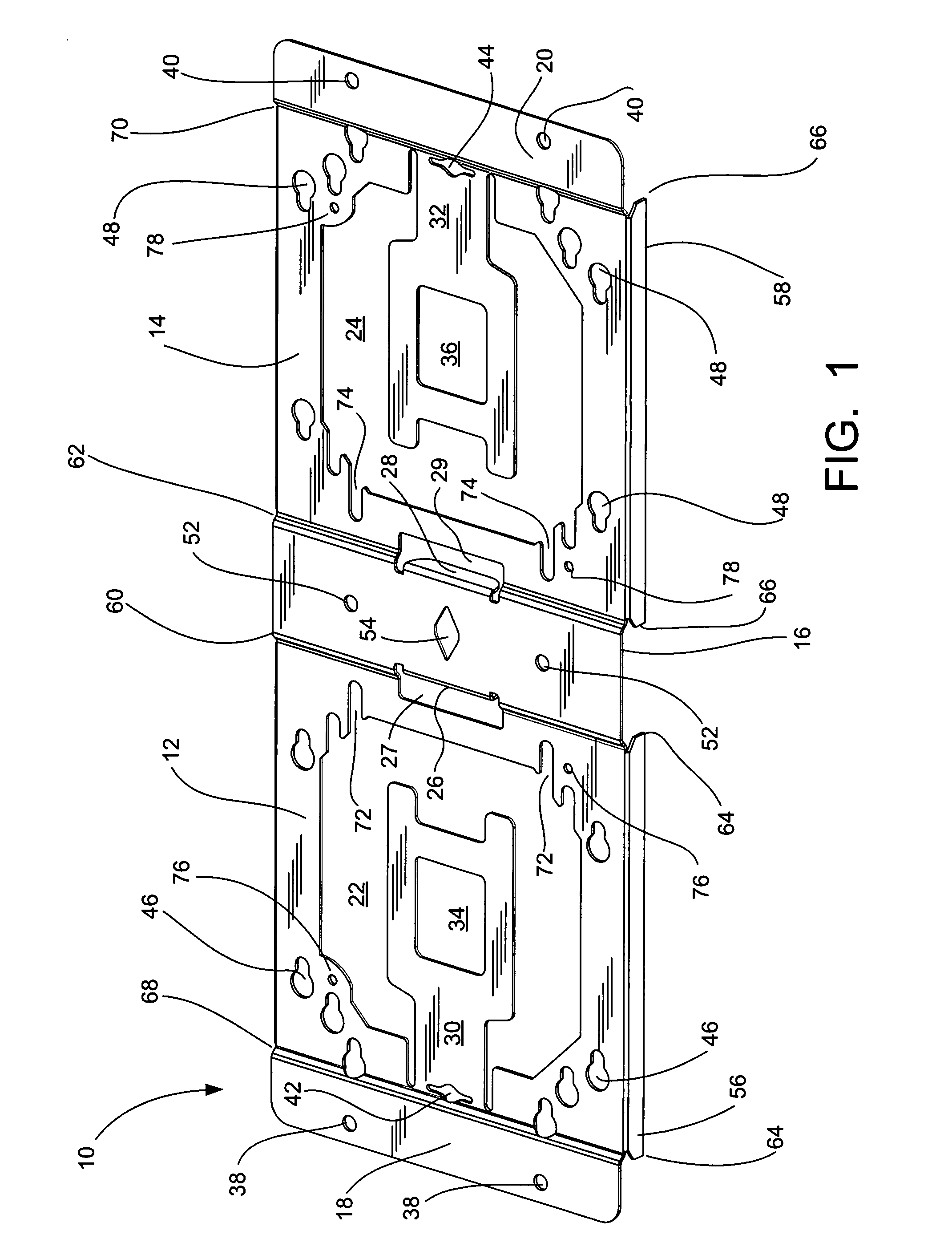
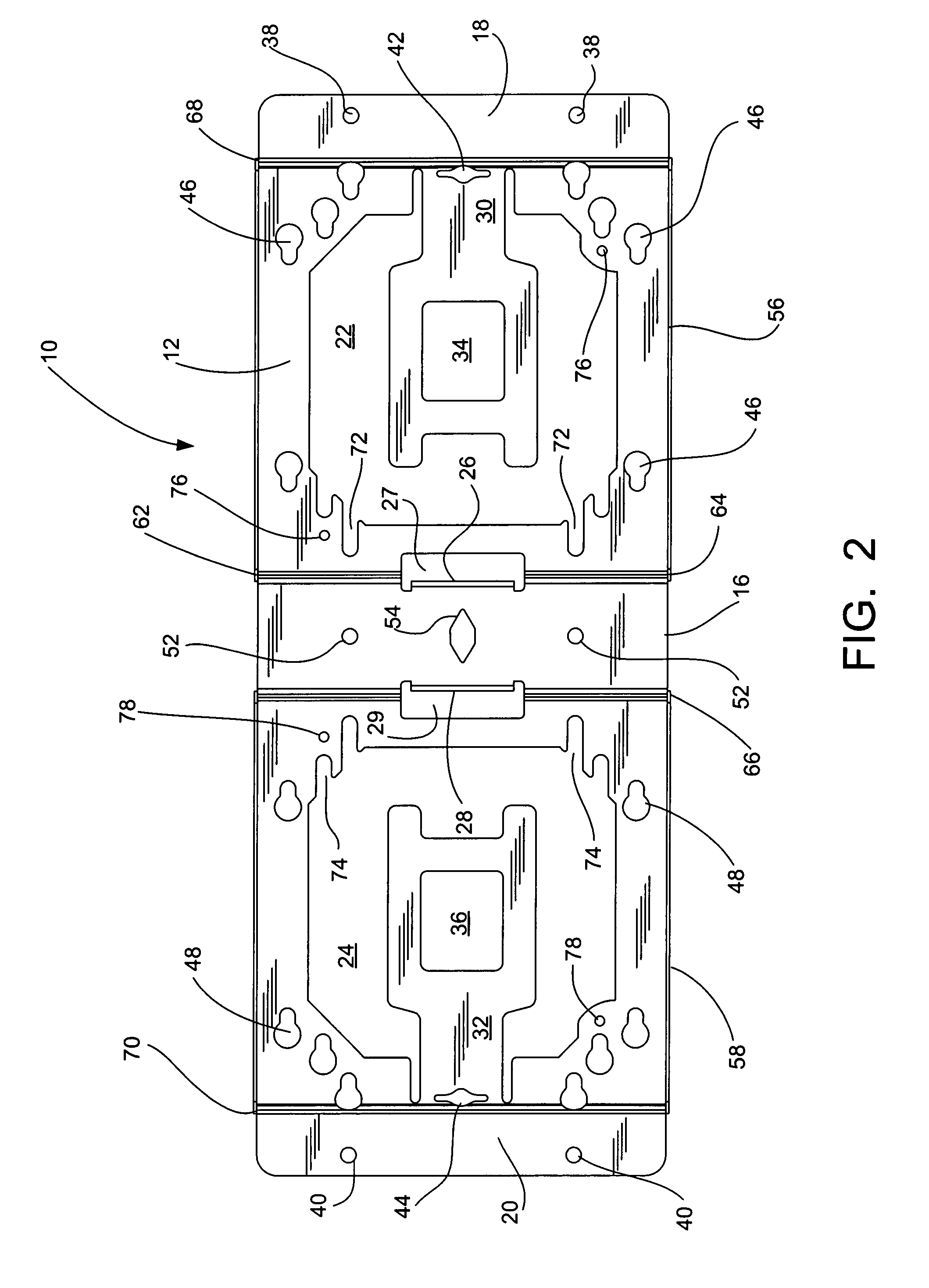
"The present invention provides a double-mounted electrical box mounting bracket that allows for secure mounting of electrical boxes to a structure. The bracket includes a flat center section, base plates, offsets, flanged ends, and flange necks. The base plates are offset and recessed from the center section and flanged ends. The bracket allows for easy installation and secure mounting of electrical boxes. The technical effects of the invention include improved stability and secure mounting of electrical boxes, as well as easy installation and versatility in mounting options."

Problems solved by technology

However, when it is desired to align the boxes horizontally, the mounting bracket used for one box can interfere with mounting the bracket for the second box.
If a bracket has a clamp (usually spring steel, etc.), placing a second electrical box directly on the opposite side from the first box becomes difficult due to the clamp taking up all of the real estate on the stud.
Due to the interference of the clamp that is used to mount the first box, the second box can only be easily attached to the stud above or below the first box—but not at the same elevation.
When a single bracket is screwed to the stud, an opposing box can be installed in the same plane by screwing a second bracket to the stud, often on top of or over the first bracket which can double the installation time and create an undesirable ‘bump’ in the final wall covering.

Method used


Image

  • Double mounted dual switch box bracket—stud divider
  • Double mounted dual switch box bracket—stud divider
  • Double mounted dual switch box bracket—stud divider

Examples


Embodiment Construction

[0014]The present invention is a double mounted dual switch box bracket that is mounted to a wall stud or similar structure so that two electrical boxes can be mounted side-by-side. The bracket includes a center section, two base plates and a pair of opposing flanged ends. The center section is connected to the first end of the base plates by a pair of offsets and the opposing flanged ends are connected to the second ends of the base plates by a pair of flange necks. The bracket allows the user to attach electrical boxes, housing a combination of low and / or high voltage devices, on opposing sides of a wall stud using only one bracket, as opposed to two separate brackets which are currently used. The opposing flanged ends of the bracket can be used to attach additional brackets for electrical boxes or they can be used to secure the bracket to another structure.

[0015]The single bracket allows base plates for two electrical boxes to be installed on either side of a wall stud using a si...


PUM


Abstract

A double-mounted electrical box mounting bracket for mounting to a wall stud that includes: a substantially flat center section having a top surface, a bottom surface, a pair of opposing sides and one or more center mounting holes for securing the bracket to a structure; a pair of substantially flat base plates, each having a first end and a second end, an opening having a periphery for receiving an electrical box, and a bendable member extending into the opening from the periphery; a pair of offsets connecting the opposing sides of the center section and the first ends of the base plates; and a pair of substantially flat flanged ends connected to the second sides of the base plates by a pair of flange necks, wherein the base plates are offset and recessed from the center section and flanged ends.

Description

FIELD OF THE INVENTION[0001]The present invention is a double mounted dual switch box bracket. In particular, the present invention relates to a double mounted dual switch box bracket that is mounted to a metal or wood wall stud.BACKGROUND OF INVENTION[0002]Electrical boxes are used for housing switches, receptacles and other types of electrical devices. In new building construction, electrical boxes are typically mounted to wall studs and separate boxes are used for low and high voltage devices in accordance with the applicable building and / or electrical codes. As a result, two or more electrical boxes can be mounted in fairly close proximity to accommodate the different voltages. When the electrical boxes are vertically aligned, they can easily be attached to the same wall stud. However, when it is desired to align the boxes horizontally, the mounting bracket used for one box can interfere with mounting the bracket for the second box.[0003]The current method of attaching electrica...

Claims


Application Information

Patent Timeline
Patent Type & Authority Patents(United States)
IPC IPC(8): A47F5/00
CPCH02G3/086Y10S248/906
Inventor BORBOLLA, IAN RUBIN DE LAMAGNO, JR., JOEY D.
Owner THOMAS & BETTS INT INC
Learn More