
Frictionally mounted utility switch box masking cover

a technology for switch boxes and masks, which is applied in the direction of contact mechanisms, casings/cabinets/drawers, electrical equipment, etc., can solve the problems of inability to easily remove, inconvenient removal, and inadvertently receiving wall finishing of switch boxes, etc., and achieves the effect of convenient removal

Inactive Publication Date: 2005-09-27
BUDDY SYST
View PDF29 Cites 27 Cited by
  • Summary
  • Abstract
  • Description
  • Claims
  • Application Information

AI Technical Summary

Benefits of technology

[0019]A common approach to masking switch boxes is to simply apply masking tape to the exposed surfaces that need to be covered. However, this is a time consuming approach and usually results in residual tape and glue being left behind when the interior walls are finished. The prior art described above provides further, more elegant solutions. However, none of the approaches that are in practice or that are known in the literature provide a complete solution to this problem. This is because, what is needed is a mask that is easily applied without adhesives or tools, that is able to quickly mount to an open box of any width, and just as easily is able to mount to both the older small bat toggle switches that have been used until recently, as well as the newer type flat, wide toggle switches. Such a mask must be inexpensive, easily stored, handled and used; and conveniently, properly and economically discarded after use.
[0022]Another objective of the invention is to provide a masking cover that is able to frictionally engage a switch box or a switch mounted in the switch box by simply reversing the orientation of the cover.
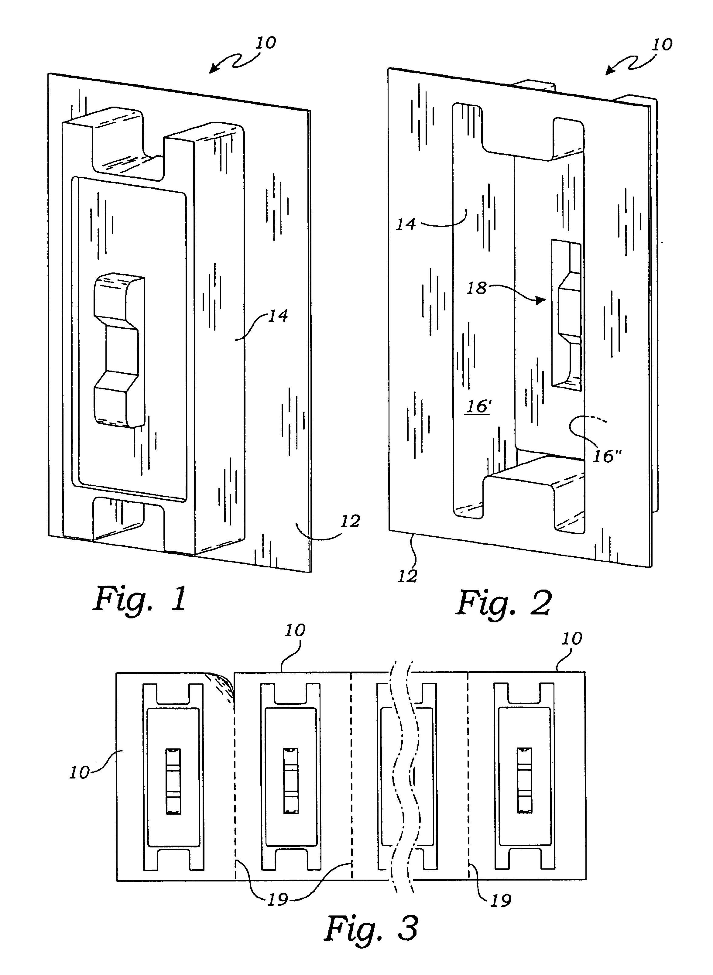
[0023]A further objective of the invention is to provide such covers in a strip which may be easily severed to detach one, two, or more of the covers for placement over a switch box having one or more switch positions or bays.
[0025]A still further objective of the invention is to manufacture the masking cover of a material that is biodegradable so that the discarding of used units does not negatively impact the environment.

Problems solved by technology

Pointedly, such boxes are subject to inadvertently receiving wall finishing materials that are placed on walls surrounding the boxes.
Materials such as wall surfacing “mud,” paint, wallpaper, wallpaper adhesive and many other items may contaminate open switch boxes.
When electrical switches are mounted and wired in open switch boxes, the problem is compounded.
However, this is a time consuming approach and usually results in residual tape and glue being left behind when the interior walls are finished.
However, none of the approaches that are in practice or that are known in the literature provide a complete solution to this problem.

Method used


Image

  • Frictionally mounted utility switch box masking cover
  • Frictionally mounted utility switch box masking cover
  • Frictionally mounted utility switch box masking cover

Examples


Embodiment Construction

[0036]The above described drawing figures illustrate the present invention in at least one of its preferred, best mode embodiments, which is further defined in detail in the following description. Those having ordinary skill in the art may be able to make alterations and modifications in the present invention without departing from its spirit and scope. Therefore, it must be understood that the illustrated embodiments have been set forth only for the purposes of example and that they should not be taken as limiting the invention as defined in the following.

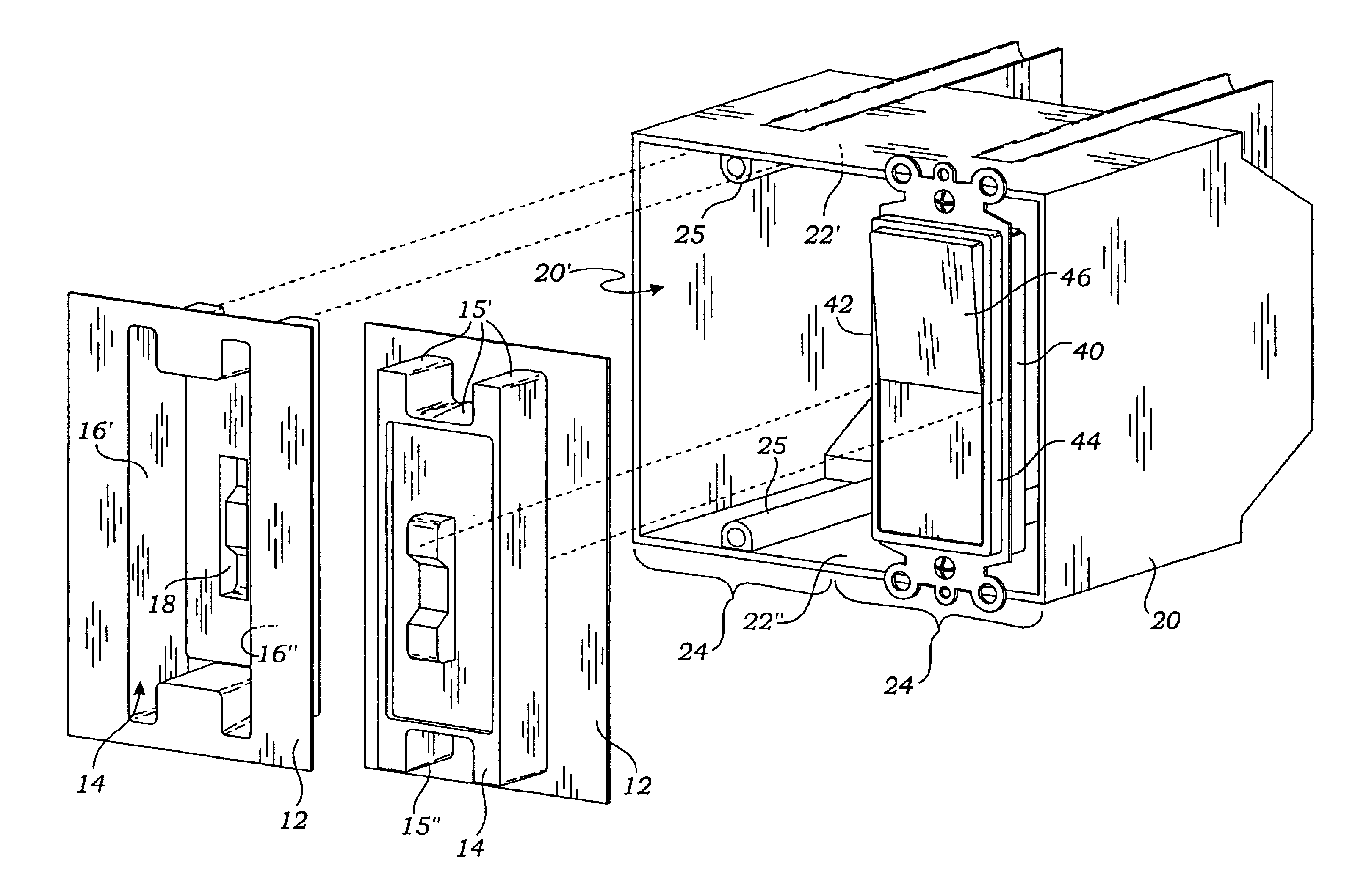
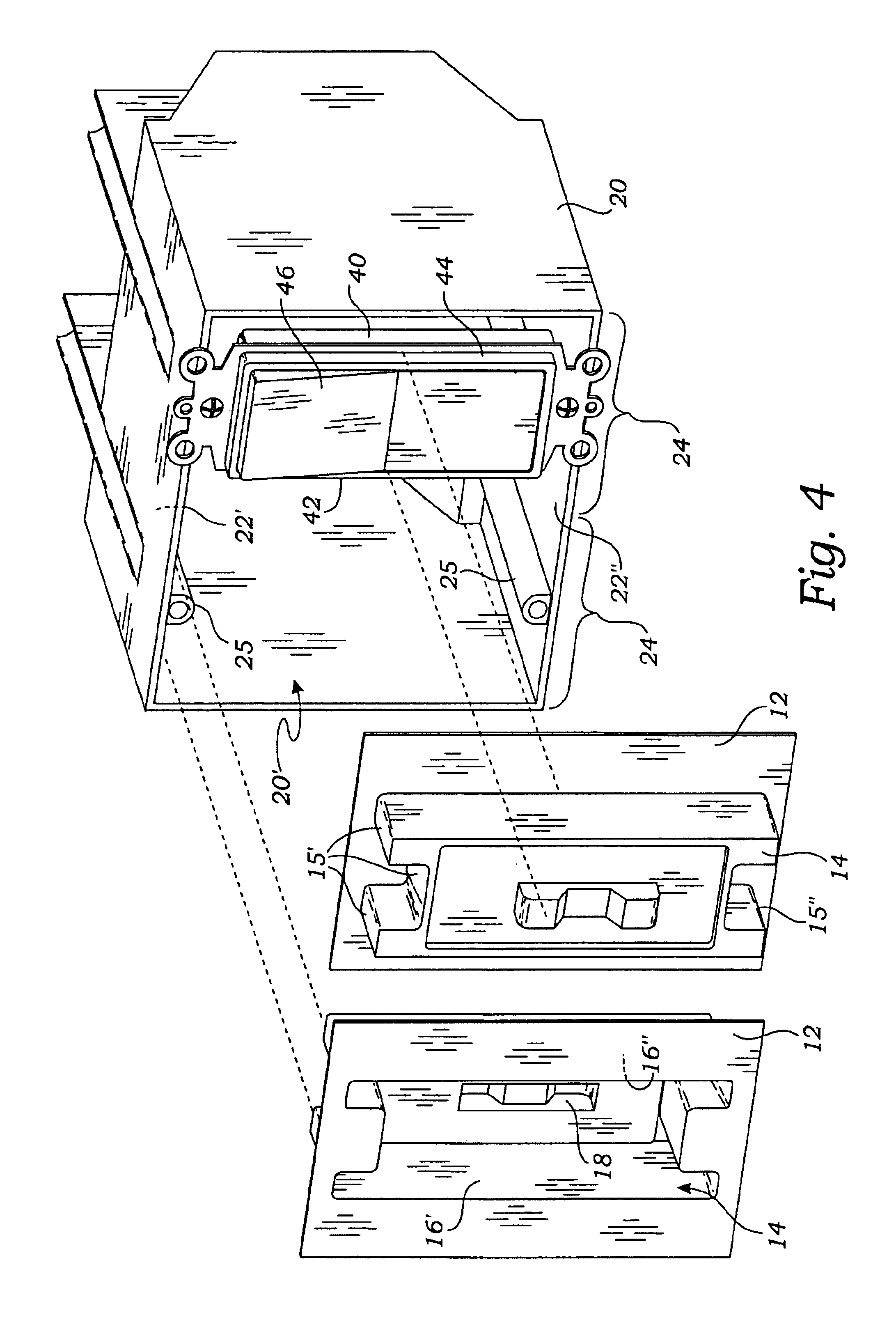
[0037]In one embodiment of the present invention a cover 10 is fabricated of thin, somewhat flexible, sheet plastic and used for covering the open face 20′ of a switch box 20 where the switch box 20 is of a type having: (1) upper 22′ (FIG. 6) and lower 22″ opposing interior surfaces, (2) at least one switch bay 24, and (3) an enablement 25, such as the bosses shown in FIGS. 4, 6 and 8, for mounting at least one switch 40. The figu...


PUM


Abstract

A switch and switch box masking cover is adapted for frictional mounting to the switch box when pressed into switch box in one orientation, and for frictional mounting to a toggle type of switch that is already mounted in the switch box, when the cover is pressed onto the switch in an alternate, reversed orientation. The masking cover is formed in continuous strips wherein one or more of the covers may be disconnected from the strip for use on a switch box of any size.

Description

RELATED APPLICATIONSIncorporation by Reference[0001]Applicant hereby incorporates herein by reference, the U.S. patents and application publications referred to in the Description of Related Art section of this application and specifically U.S. Pat. Nos.: Des. 212,093; Des. 286,739; 3,061,083; 3,601,276; 5,063,872; 5,301,437; 5,710,392; 2002 / 0157851; 6,538,202; and 2003 / 0056968.BACKGROUND OF THE INVENTION[0002]1. Field of the Invention[0003]This invention relates generally to painting masks and similar disposable covers, and more particularly to a switch box cover of molded construction and formed as a thin sheet with a depressed portion having a conformation that allows the cover to mask an empty switch box bay or a bay having a switch mounted therein. The invention further is related to the field of strip mounted units that are manually separable from the strip as one or more connected units.[0004]2. Description of Related Art[0005]The following art defines the present state of th...

Claims


Application Information

Patent Timeline
Patent Type & Authority Patents(United States)
IPC IPC(8): H01H9/20H02G3/14H01H9/28
CPCH02G3/14H01H9/287
Inventor HAUSEN, DANIEL M.SPEHAR, ELI GEOFFREY
Owner BUDDY SYST
Learn More