Robotic vacuum cleaner with edge and object detection system

a robot vacuum cleaner and object detection technology, applied in the field of sensors, can solve the problems of difficult real-time mapping of the environment of the robot using such sensors, and difficult to do relatively complex calculations

Inactive Publication Date: 2010-09-21
SHARPER IMAGE ACQUISITION
View PDF128 Cites 146 Cited by
  • Summary
  • Abstract
  • Description
  • Claims
  • Application Information

AI Technical Summary

Problems solved by technology

Mapping the environment of a robot using such sensors can be difficult.
Such relatively complex calculations can be difficult to do in real-time especially when other software processes needs to be executed on the robot.

Method used


Image

  • Robotic vacuum cleaner with edge and object detection system
  • Robotic vacuum cleaner with edge and object detection system
  • Robotic vacuum cleaner with edge and object detection system

Examples


Embodiment Construction

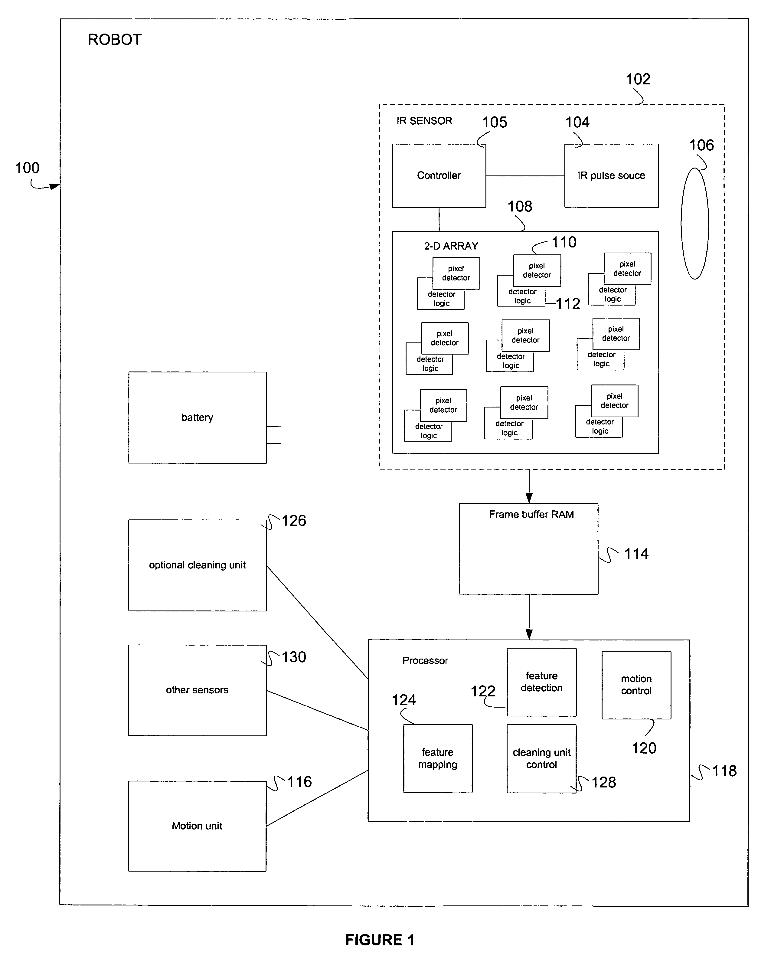
[0024]FIG. 1 illustrates one example of a Robot 100. In the example of FIG. 1, the Robot 100 includes a motion unit 116. The motion unit 116 can be for example, wheels, tracks, legs or any element to move the robot 100. In one embodiment, the processor 118 uses motion control software 120 to control the motion unit 116. The motion unit 116 can include wheels, tracks, wings, legs or any other means of locomotion. The robot 100 also includes an IR sensor 102.

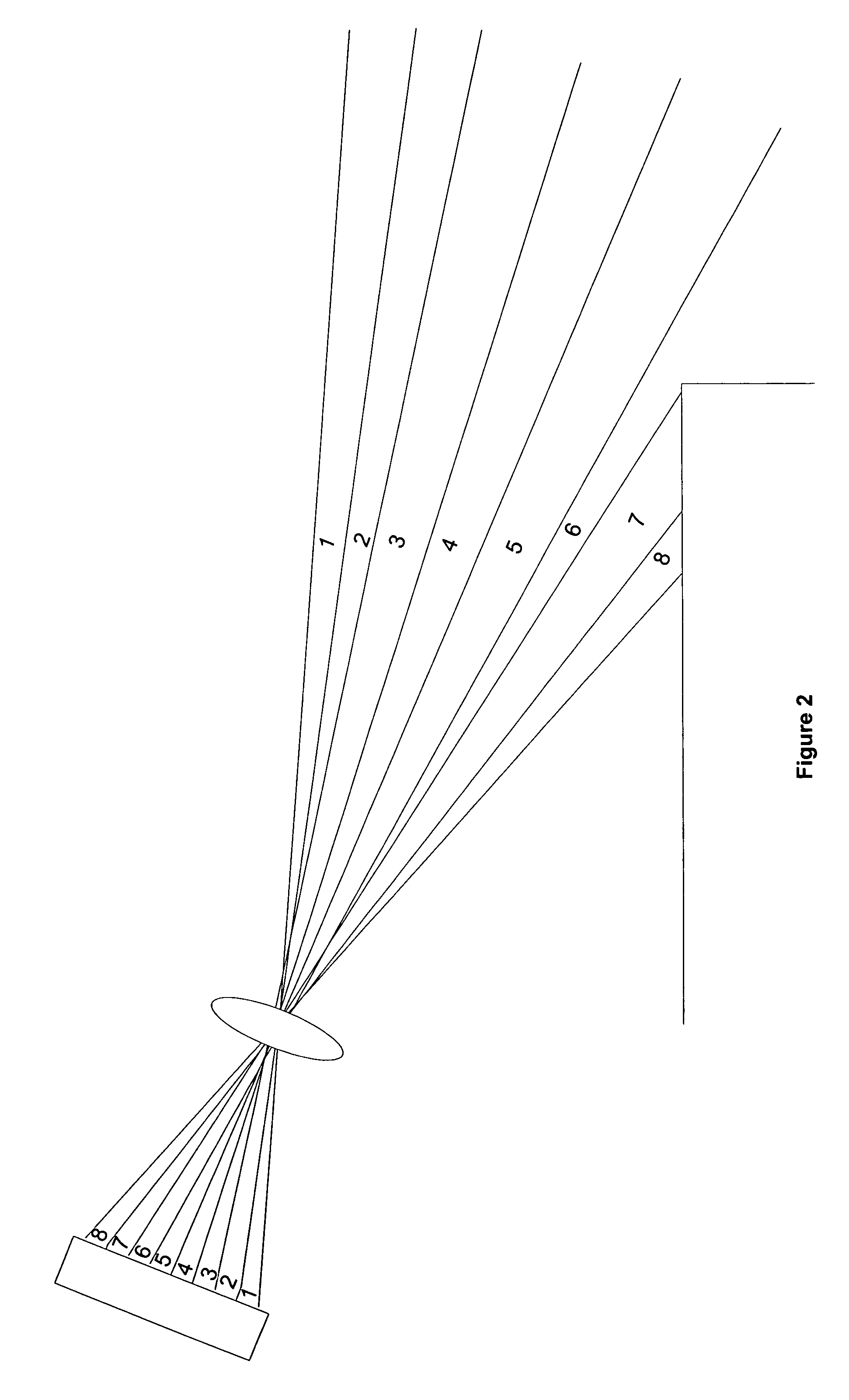
[0025]An infrared sensor 102 includes an infrared light source 104. The infrared light source 104 can produce pulses of infrared light. An infrared light sensor 102 includes optics 106 to focus reflections from an infrared light source pulse from different portions of the environment to different detectors in a two dimensional (2D) array of the detectors 108. The optics 106 can include a single or multiple optical elements. In one embodiment, the optics 106 focus light reflected from different regions of the environment to the det...


PUM


Abstract

A robot uses an infrared sensor including an infrared light source which produces pulses of infrared light. Optics focus reflections of the infrared light pulses from different portions of the environment of the robot to different detectors in a 2D array of detectors. The detectors produce an indication of the distance to the closest object in an associated portion of the environment. The robot can use the indications to determine features in the environment. The robot can be controlled to avoid these features.

Description

CLAIM OF PRIORITY[0001]This application claims priority to U.S. Patent Provisional Application No. 60 / 454,934 filed Mar. 14, 2003; U.S. Provisional Application No. 60 / 518,756 filed Nov. 10, 2003; U.S. Provisional Application No. 60 / 518,763 filed Nov. 10, 2003; U.S. Provisional Application No. 60 / 526,868 filed Dec. 4, 2003; U.S. Provisional Application No. 60 / 527,021 filed Dec. 4, 2003 and U.S. Provisional Application No. 60 / 526,805 filed Dec. 4, 2003. This application incorporates by reference U.S. application Ser. No. 10 / 798,232 entitled “Robot Vacuum” by Taylor et al., filed concurrently and published as US Pub.20040244138, which has been abandoned.[0002]This application is related to the following commonly owned, co-pending applications:CROSS REFERENCE TO RELATED APPLICATIONS[0003]U.S. Patent Appln. Nos. Filed[0004]Ser. No. 10 / 798,232 Mar. 11, 2004[0005]Ser. No. 10 / 799,916 Mar. 11, 2004[0006]Ser. No. 10 / 798,732 Mar. 11, 2004[0007]Ser. No. 10 / 798,716 Mar. 11, 2004[0008]Ser. No. 10...

Claims


Application Information

Patent Timeline
Patent Type & Authority Patents(United States)
IPC IPC(8): G05B15/00G06F19/00
CPCG01S17/10G01S17/936G05D1/0242G05D2201/0215G01S17/931
Inventor TAYLOR, CHARLES E.PARKER, ANDREW J.LAU, SHEK FAIBLAIR, ERIC C.HENINGER, ANDREWNG, ERICBRENNER, PATRICIA I.
Owner SHARPER IMAGE ACQUISITION
Why Eureka
Try Eureka