Controlling motion using a human machine interface

a human machine interface and interface technology, applied in the field of human machine interface control, can solve the problems of lack of research or development on applying ethnographic techniques and user studies to human machine interfaces, lack of strong user task concepts, and inability to adequately draw on notions in most human machine interfaces

Active Publication Date: 2010-09-21
NAT TECH & ENG SOLUTIONS OF SANDIA LLC
View PDF6 Cites 20 Cited by
  • Summary
  • Abstract
  • Description
  • Claims
  • Application Information

AI Technical Summary

Benefits of technology

[0010]Accordingly, the invention improves on the prior art by providing a method for establishing the position of an icon in a 3D environment, the method comprising the steps of: establishing an icon in a first view of the 3D environment, wherein the first view is centered at a viewpoint; displaying the icon in a second view having a second perspective such that the icon is rendered in a corresponding a 3D position of the icon as viewed in the second view; defining a polar coordinate system having three axes centered at the viewpoint, wherein a first axis and a second axis is displayed in the first view and a third axis constrained to a radial direction is displayed in the second view; and moving the icon, wherein movement of the icon is constrained to the first axis and second axis in the first view and the third axis in the second view.

Problems solved by technology

However, relatively little research or development has been done to apply HCI user studies and ethnographic techniques to Human Machine Interfaces.
After analyzing several human machine interfaces on typical existing robot systems against a variety of user needs, it can be seen that most human machine interfaces lack a strong concept of user tasks and do not adequately draw on notions that are familiar to the community of users of robotic equipment for task handing such as robot handlers in the bomb squad user community and the like.
Modern HMIs do not accommodate typical practices such as task orientation and sketch generation, and often the HMI imposes a layer of complexity between actually performing the task and controlling robotic, machine and / or virtual object motion.

Method used


Image

  • Controlling motion using a human machine interface
  • Controlling motion using a human machine interface
  • Controlling motion using a human machine interface

Examples


Embodiment Construction

[0024]Aspects of the invention are disclosed in the accompanying description. Alternate embodiments can be devised without departing from the spirit or the scope of the invention. Further, those skilled in the art will appreciate that well-known systems and methods will not be described in detail herein.

[0025]Although the following description is made with reference mainly to a robotic device, those skilled in the art will appreciate that the present invention can be used with any machine or virtual system that can be moved in at least three dimensions.

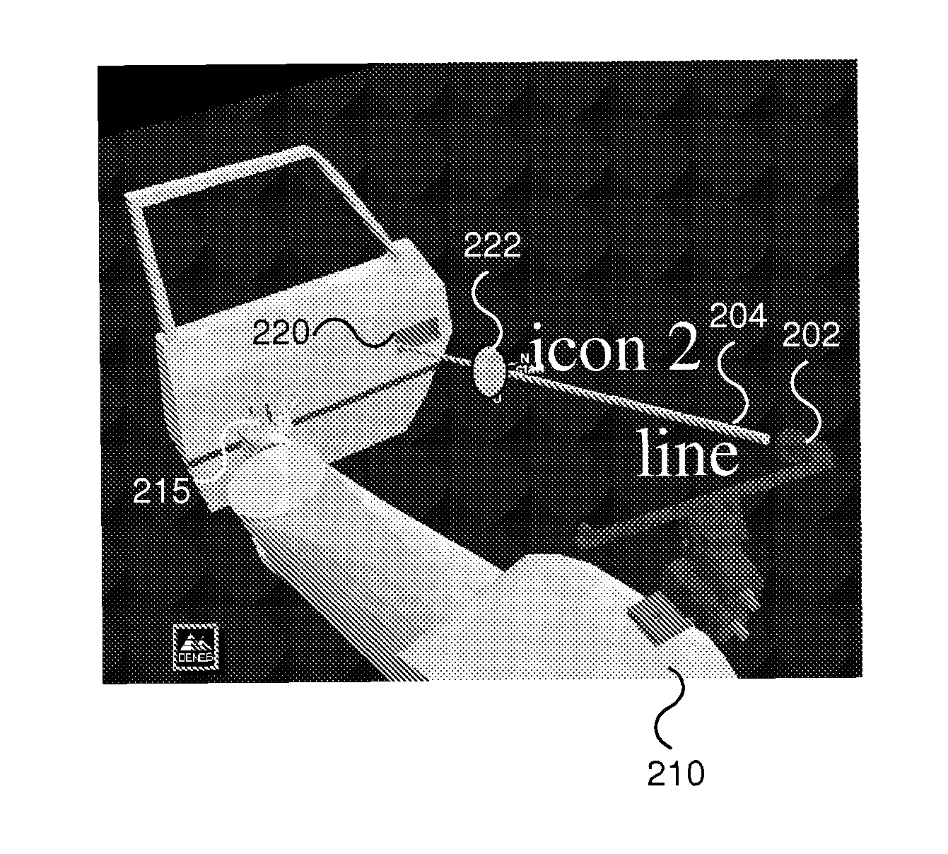
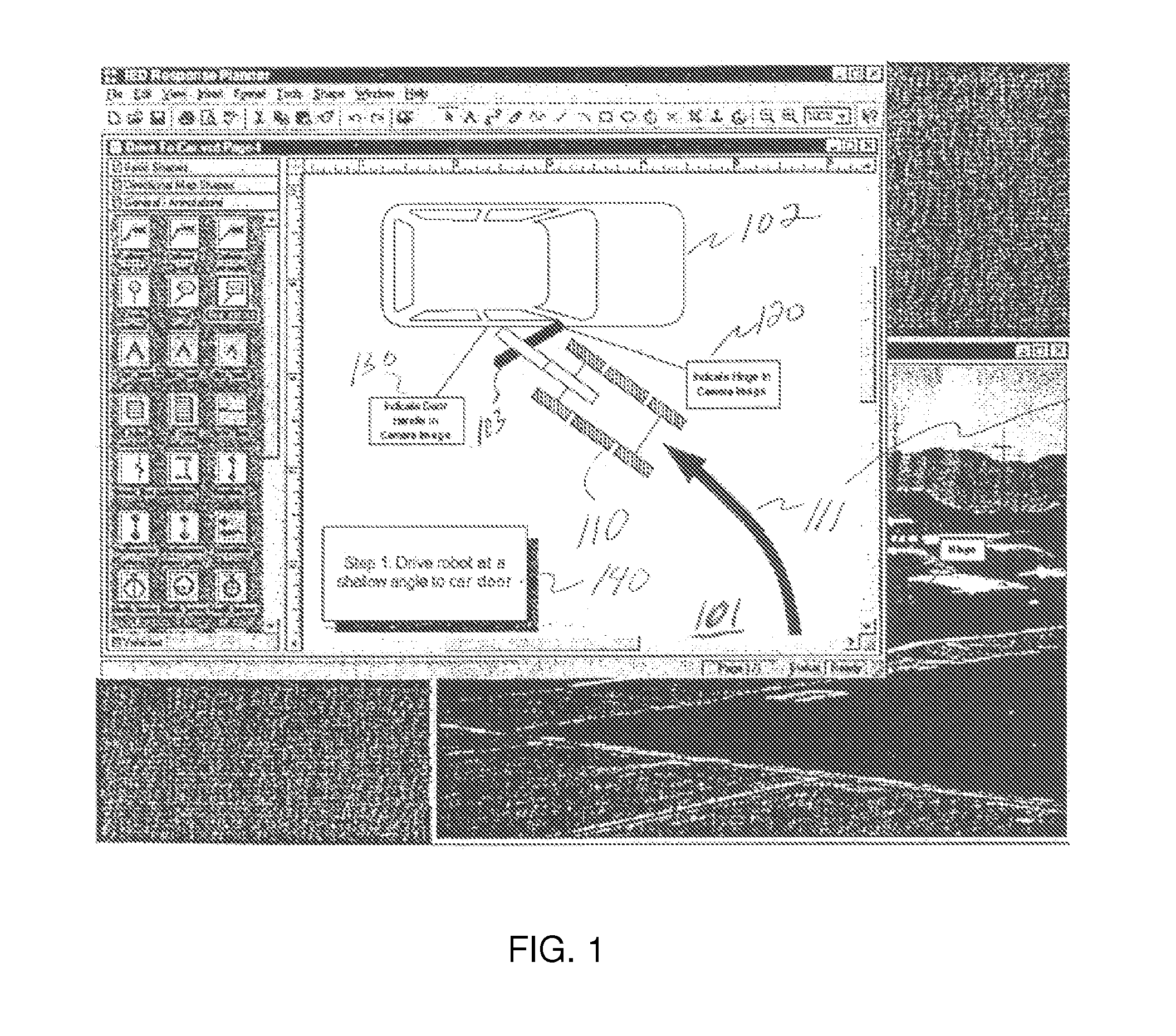
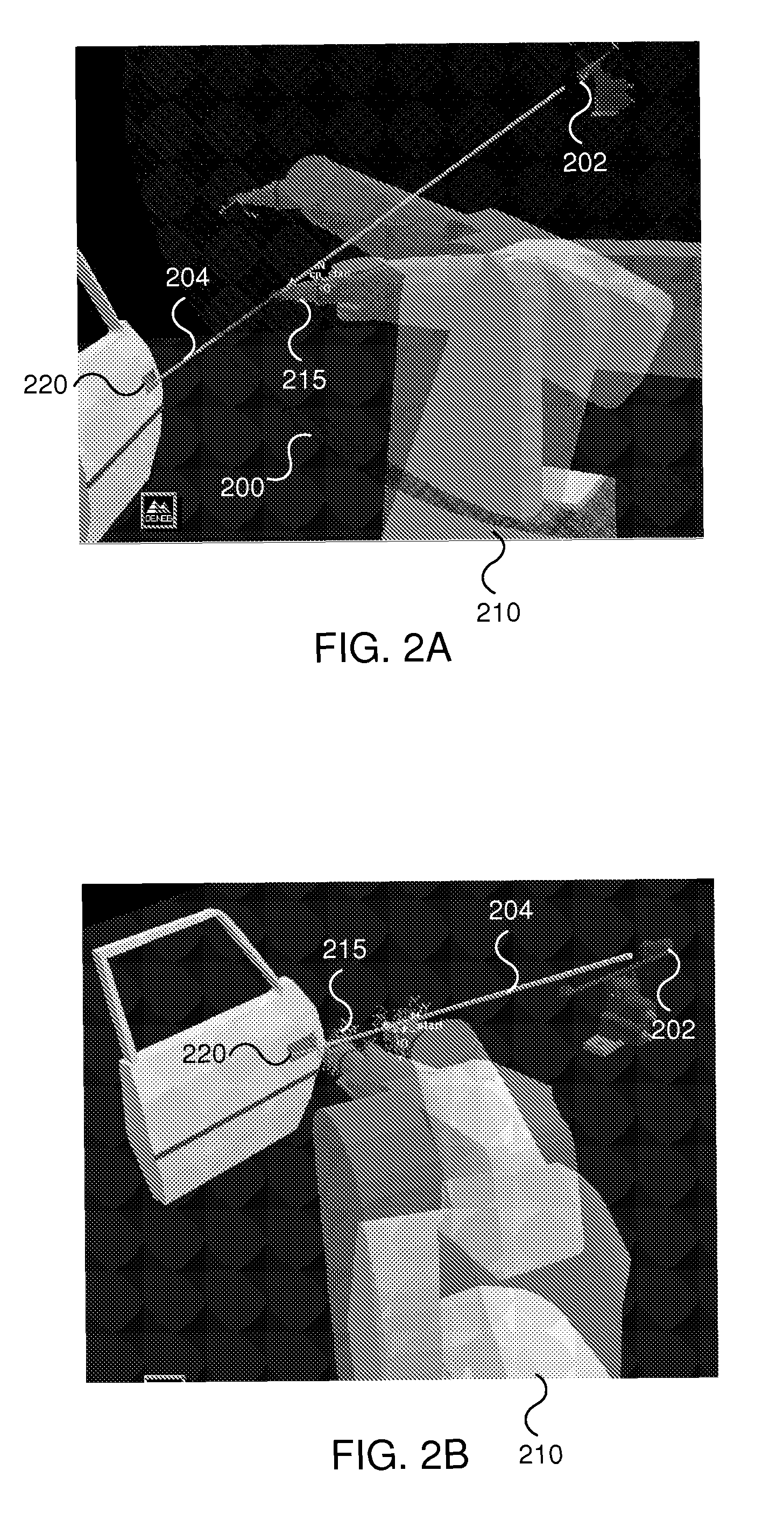
[0026]A method and apparatus are described whereby in simply stated terms whereby a user can interact with a graphical HMI interface (e.g., containing sketches, views, 3D CAD elements, images, and the like) to direct motion and task accomplishment associated with a robot, machine or virtual device. An operator can, for example, modify pre-built sketches representing best practices into sketches describing a current situation. In accor...


PUM


Abstract

Machine motion is directed using a graphical interface by establishing an icon in an image, displaying the icon in images having perspectives such that the icon is rendered in a corresponding relative position in the second images and moving the icons in the second images when the icon is moved in the first image, the movement being constrained along a line projected from a camera point associated with the first image and a target destination. Actions are defined using the icon and a set of action descriptors. The dominant motion space is constrained to a spherical coordinate frame centered on a vision locus and machine motions are mapped to coincide therewith based on a graphical interface view.

Description

RELATED APPLICATIONS[0001]This application claims priority under 35 U.S.C. §119(e) of U.S. Provisional Application 60 / 340,876 filed on Dec. 19, 2001, the entire content of which is herein incorporated by reference. This application is a Continuation In Part of U.S. application Ser. No. 10 / 324,411 filed on Dec. 17, 2002, now abandoned, the entire content of which is herein incorporated by reference.FEDERALLY SPONSORED RESEARCH[0002]The United States Government has rights in this invention pursuant to Department of Energy Contract No. DE-AC04-94AL85000 with Sandia Corporation.FIELD OF THE INVENTION[0003]The present invention relates to control of motion using a Human Machine Interface (HMI). In particular, the present invention relates to directing a virtual, robotic, or machine element's motion directly through a graphical human machine interface.BACKGROUND OF THE INVENTION[0004]Human Machine Interfaces (HMIs) for intelligent machines and robots is an active research topic with liter...

Claims


Application Information

Patent Timeline
Patent Type & Authority Patents(United States)
IPC IPC(8): G06F3/048
CPCB25J9/1689G06F3/04815G06F3/04845G06T19/00G05B2219/35506G05B2219/37567G05B2219/40161G05B2219/40169
Inventor MCDONALD, MICHAEL J.GLADWELL, T. SCOTTANDERSON, ROBERT J.
Owner NAT TECH & ENG SOLUTIONS OF SANDIA LLC
Why Eureka
Try Eureka