Compact multiple transformers

a transformer and compact technology, applied in the field of transformers, can solve the problems of increasing manufacturing cost, chip size, package size, and the size of multiple transformers, and achieve the effect of increasing the magnetic flux, inductance, and/or quality factor of the transformer

Inactive Publication Date: 2010-10-12
SAMSUNG ELECTRO MECHANICS CO LTD +1
View PDF48 Cites 167 Cited by
  • Summary
  • Abstract
  • Description
  • Claims
  • Application Information

AI Technical Summary

Benefits of technology

[0003]Example embodiments of the invention may provide for compact multiple transformers, where each transformer of the multiple transformers may include a primary winding and a secondary winding. A first transformer may be coupled to at least one other second transformer, where the first outer metal lines of the first transformer may be coupled to the second outer metal lines of the at least one other second transformer, where the first outer metal lines and the second outer metal lines may provide for a same current flow direction. The same current flow direction may increase magnetic flux, inductance, and / or quality factor of the transformers.

Problems solved by technology

In the semiconductor technology, a monolithic transformer requires a significant amount of space.
Accordingly, the total size of multiple transformers is large and increases manufacturing cost, chip size, and package size.

Method used


Image

  • Compact multiple transformers
  • Compact multiple transformers
  • Compact multiple transformers

Examples


Embodiment Construction

[0015]Example embodiments of the invention now will be described more fully hereinafter with reference to the accompanying drawings, in which some, but not all embodiments of the invention are shown. Indeed, these inventions may be embodied in many different forms and should not be construed as limited to the embodiments set forth herein; rather, these embodiments are provided so that this disclosure will satisfy applicable legal requirements. Like numbers refer to like elements throughout.

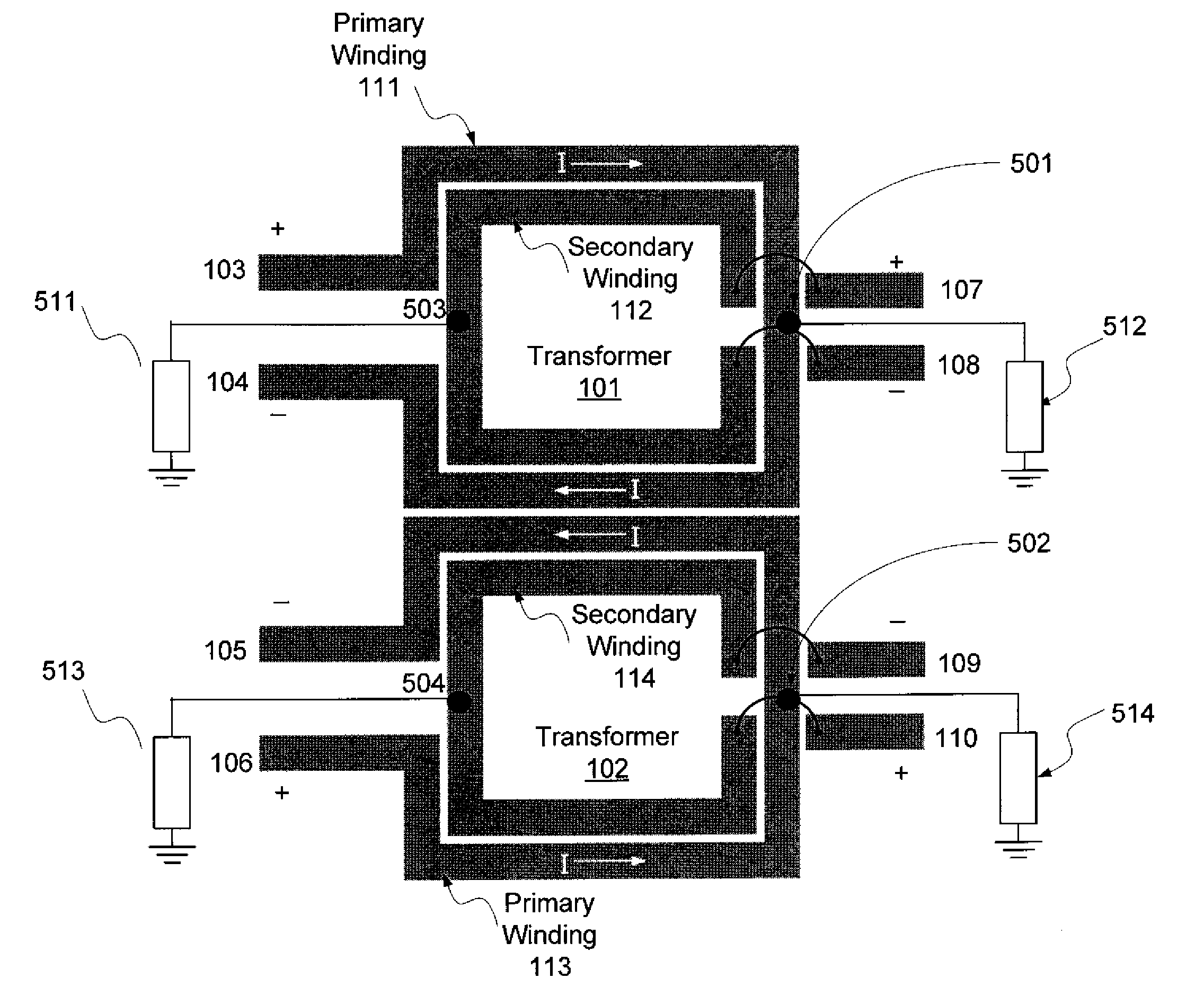
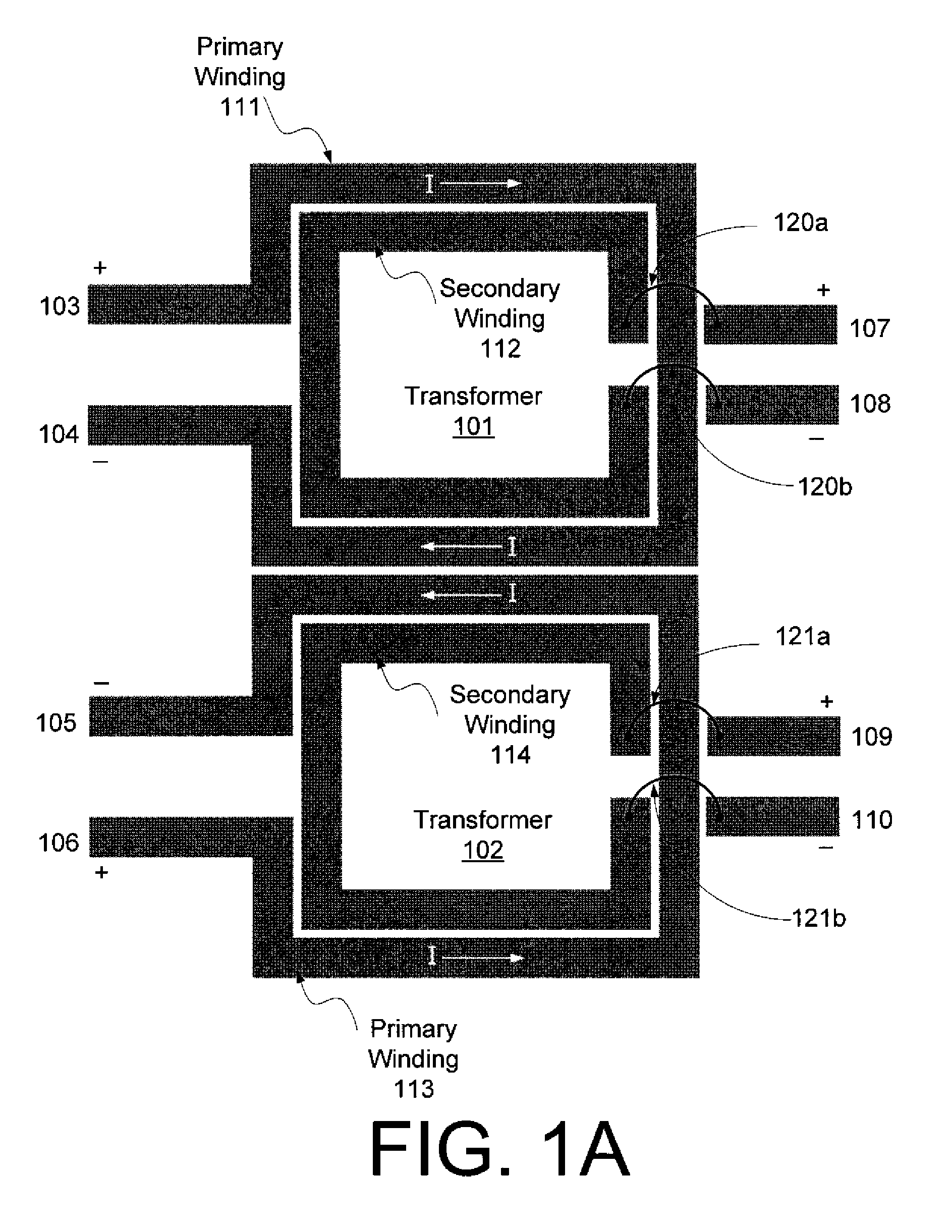
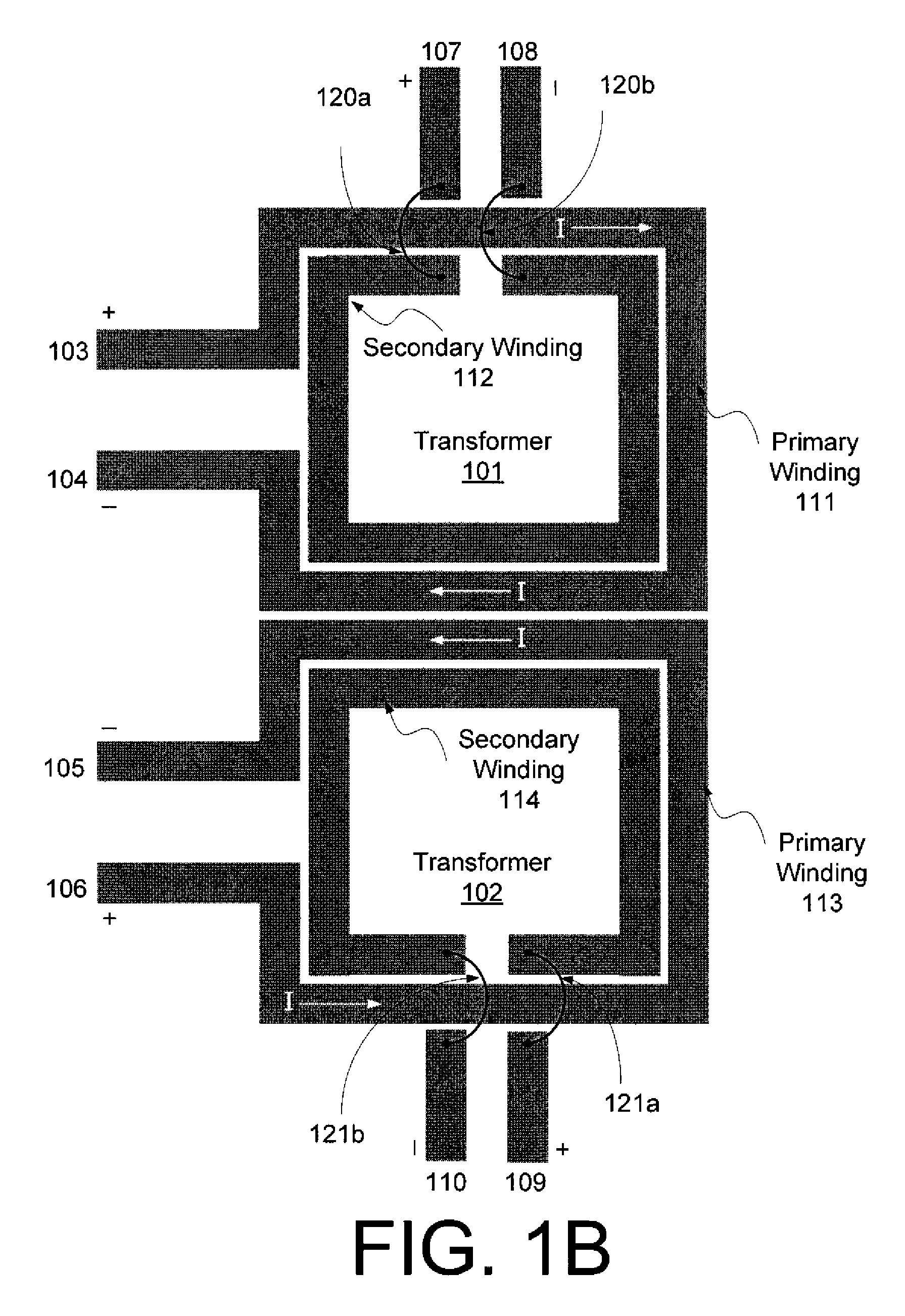
[0016]FIG. 1A illustrates example compact multiple transformers, including a first transformer 101 and a second transformer 102, according to an example embodiment of the invention. As shown in FIG. 1A, the example compact multiple transformers may include a first transformer 101 that includes a primary winding 111 and a secondary winding 112. The primary winding 111 may receive input signals from a first input port 103 that may receive a positive input signal and a second input port 104 that may ...


PUM

PropertyMeasurementUnit
separation distanceaaaaaaaaaa

Abstract

Example embodiments of the invention may provide systems and methods for multiple transformers. The systems and methods may include a first transformer that may include a first primary winding and a first secondary winding, where the first primary winding may be inductively coupled to the first secondary winding, where the first transformer may be associated with a first rotational current flow direction in the first primary winding. The systems and methods may further include a second transformer that may include a second primary winding and a second secondary winding, where the second primary winding may be inductively coupled to the second secondary winding, where the second transformer may be associated with a second rotational current flow direction opposite the first rotational current flow direction in the second primary winding, where a first section of the first primary winding may be positioned adjacent to a second section of the second primary winding, and where the adjacent first and second sections may include a substantially same first linear current flow direction.

Description

FIELD OF INVENTION[0001]The invention relates generally to transformers, and more particularly, to systems and methods for compact multiple transformers.BACKGROUND OF THE INVENTION[0002]According to the fast growth of semiconductor technology, many blocks and functions have been integrated on a chip as a System-On-Chip (SOC) technology. In the semiconductor technology, a monolithic transformer requires a significant amount of space. Moreover, the monolithic transformer requires a minimum of 50-μm spacing from other circuitry to prevent undesirable magnetic coupling or loss of magnetic flux. Accordingly, the total size of multiple transformers is large and increases manufacturing cost, chip size, and package size.BRIEF SUMMARY OF THE INVENTION[0003]Example embodiments of the invention may provide for compact multiple transformers, where each transformer of the multiple transformers may include a primary winding and a secondary winding. A first transformer may be coupled to at least o...

Claims


Application Information

Patent Timeline
Patent Type & Authority Patents(United States)
IPC IPC(8): H01F5/00
CPCH01F27/2804H01F5/003H01F38/42H01F21/12
Inventor LEE, DONG HOYANG, KI SEOKLEE, CHANG-HOKIM, HAKSUNLASKAR, JOY
Owner SAMSUNG ELECTRO MECHANICS CO LTD
Why Eureka
Try Eureka