Racking mechanism for a circuit breaker

a circuit breaker and rack mechanism technology, applied in the field of rack mechanisms, can solve the problems of over-exertion of ergonomic limitations, increased force needed, etc., and achieve the effect of reducing the number of racks

Active Publication Date: 2010-10-26
ABB SPA
View PDF43 Cites 19 Cited by
  • Summary
  • Abstract
  • Description
  • Claims
  • Application Information

AI Technical Summary

Benefits of technology

[0004]A racking mechanism for a drawout circuit breaker includes a cross shaft movably positioned in an enclosure and at least one input link in operable communication with the cross shaft. At least one racking cam is movably positioned in the enclosure and is in operable communication with the input link via at least one connecting link. Each racking cam has at least one cam slot receptive of a portion of a circuit breaker. Movement of the cross shaft about a cross shaft axis is capable of moving the at least one racking cam from an open position toward a closed position with the portion of the circuit breaker disposed in the at least one cam slot, thereby securing the circuit breaker in the enclosure.
[0006]A circuit breaker assembly includes an enclosure, a circuit breaker insertable in the disclosure; and a racking mechanism. The racking mechanism includes a cross shaft movably positioned in the enclosure and at least one input link is in operable communication with the cross shaft. At least one racking cam is movably positioned in the enclosure and is in operable communication with the input link. Each racking cam has at least one cam slot receptive of a portion of the circuit breaker. Movement of the cross shaft about a cross shaft axis is capable of moving the at least one racking cam from an open position toward a closed position with the portion of the circuit breaker disposed in the at least one cam slot, thereby securing the circuit breaker in the enclosure.

Problems solved by technology

Typical racking mechanisms often require a high force be applied to rack the circuit breaker, and the amount of force necessary often increases as the number of electrical contacts to be engaged increases.
As the number of contacts is increased, the force that, for example, a technician must apply to actuate a typical racking mechanism may exceed ergonomic limitations.
Further, during fault situations, a typical racking mechanism often allows the circuit breaker to be pushed out and disconnected from the electrical contacts as a result of electromotive forces occurring during the fault.

Method used


Image

  • Racking mechanism for a circuit breaker
  • Racking mechanism for a circuit breaker
  • Racking mechanism for a circuit breaker

Examples


Embodiment Construction

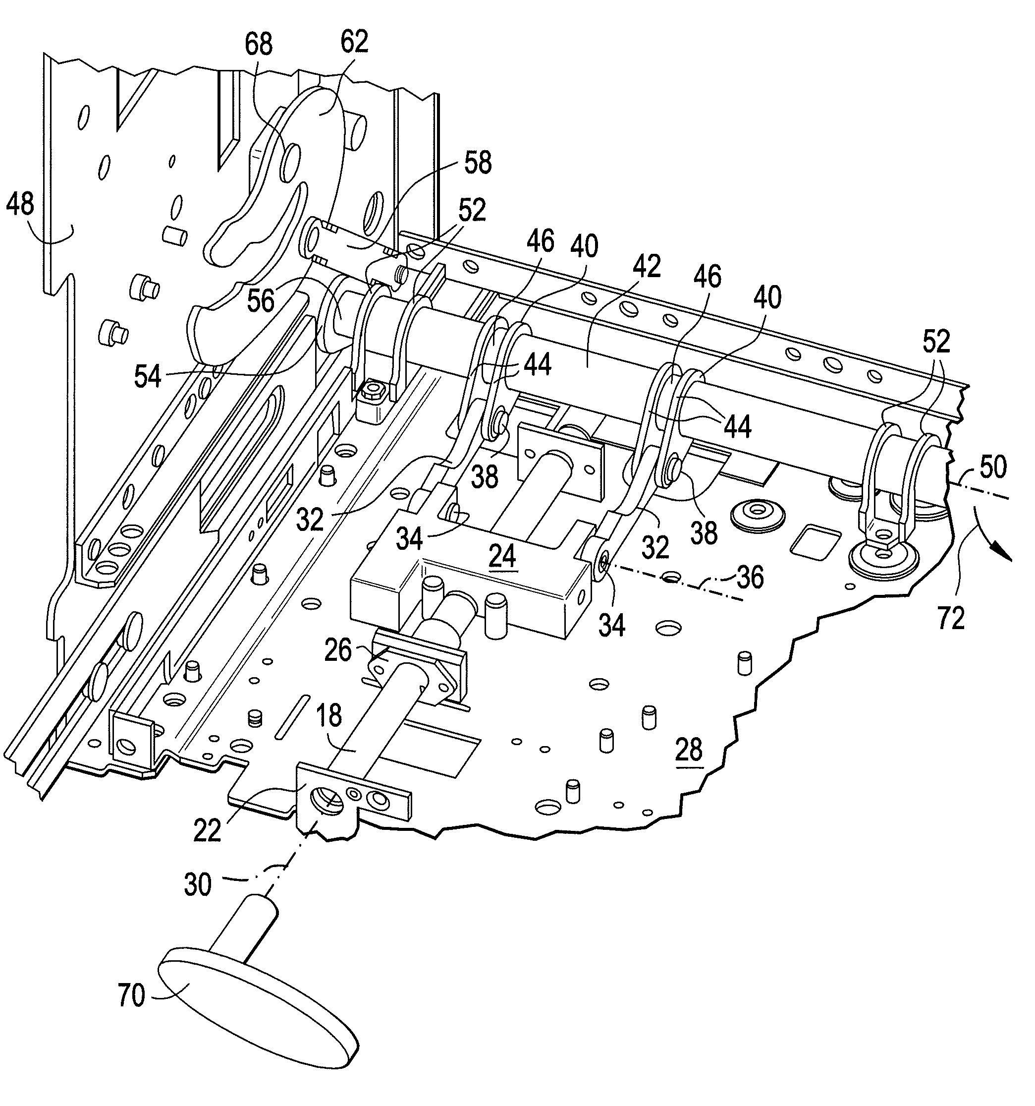
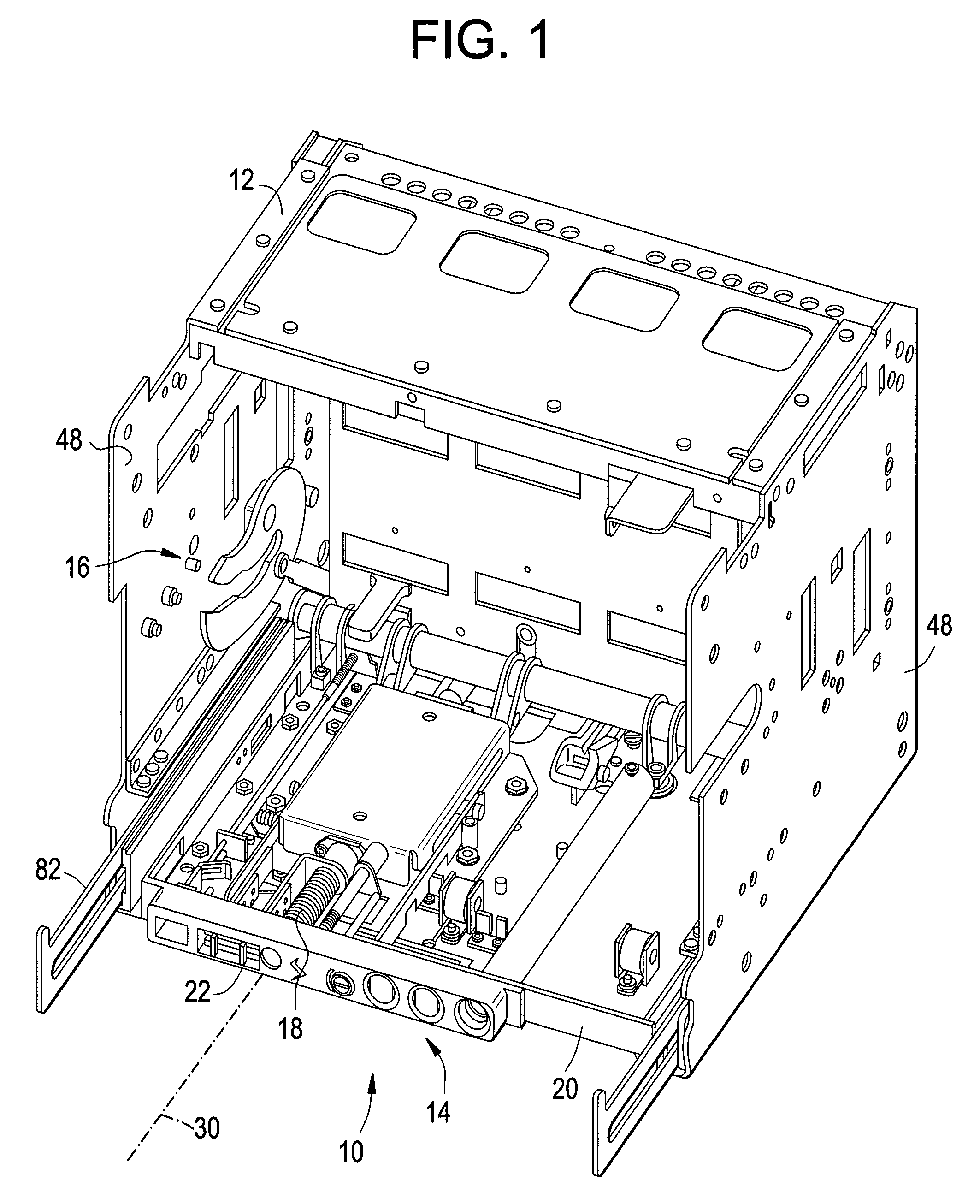
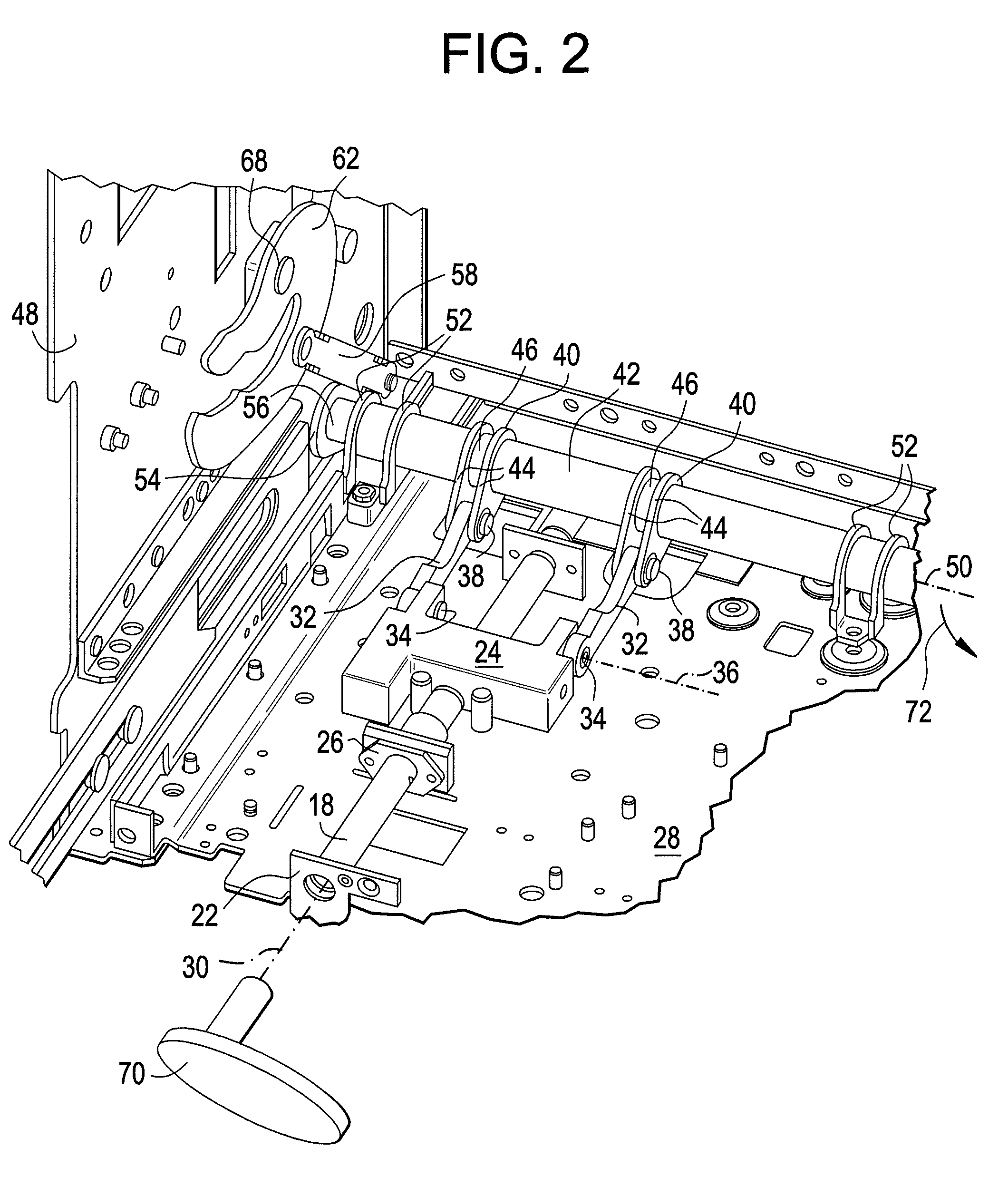
[0018]Shown in FIG. 1 is an embodiment of a racking mechanism 10 disposed in a draw out circuit breaker cassette 12. The racking mechanism 10 includes a drive unit 14 and a locking unit 16. The drive unit 14 of the embodiment shown in FIG. 1 includes a racking screw 18 extending into the cassette 12 from a cassette face 20 through a cassette face hole 22. Referring now to FIG. 2, the racking screw 18 is connected to a screw bearing 24. Between the cassette face 20 and the screw bearing 24, the racking screw 18 may pass through one or more supports 26 to maintain alignment of the racking screw 18. The screw bearing 24 is slidably disposed at a cassette base 28, and transfers rotational motion of the racking screw 18 into linear motion of the screw bearing 24 along, for example, racking screw axis 30. The screw bearing 24 is connected to one or more connecting links 32 by, for example, a connecting pin 34. The connecting pin 34 allows for relative rotative movement of the connecting l...


PUM


Abstract

Disclosed is a racking mechanism for a drawout circuit breaker including a cross shaft movably positioned in an enclosure and at least one input link in operable communication with the cross shaft via at least one connecting link. At least one racking cam is movably positioned in the enclosure and is in operable communication with the input link. Each racking cam has at least one cam slot receptive of a portion of the circuit breaker. Movement of the cross shaft about an axis of the cross shaft is capable of moving the at least one racking cam from an open position toward a closed position with the portion of the circuit breaker disposed in the at least one cam slot, thereby securing the circuit breaker in the enclosure and the at least one racking cam is in the closed position. A method for securing a circuit breaker in an enclosure and a circuit breaker assembly are also disclosed.

Description

BACKGROUND[0001]The subject invention relates to circuit breakers. More particularly, the subject invention relates to racking mechanisms for draw out circuit breakers.[0002]Draw out circuit breakers often include a mechanism for drawing the breaker in and connecting the breaker to corresponding electrical contacts. The mechanism is reversed to disconnect the circuit breaker from the electrical contacts when, for example, maintenance is performed along an electrical network to which the circuit breaker is connected. Typical racking mechanisms often require a high force be applied to rack the circuit breaker, and the amount of force necessary often increases as the number of electrical contacts to be engaged increases. As the number of contacts is increased, the force that, for example, a technician must apply to actuate a typical racking mechanism may exceed ergonomic limitations.[0003]Further, during fault situations, a typical racking mechanism often allows the circuit breaker to ...

Claims


Application Information

Patent Timeline
Patent Type & Authority Patents(United States)
IPC IPC(8): H02B11/127H01H9/20
CPCH02B11/127
Inventor NARAYANASAMY, SOUNDARARAJANNARAYANAN, JANAKIRAMANNEWASE, YATIN VILASDODDAPADAM SRINIVASA RAGHAVACHAR, PARTHA SARATHY
Owner ABB SPA
Why Eureka
Try Eureka