Adjustable stride length exercise method and apparatus

a stride length and adjustable technology, applied in the direction of gymnastic exercise, sport apparatus, frictional force resistor, etc., can solve the problems of perceived quality of exercise exceeding actual quality of exercise, and relatively difficult use of exercise apparatus

Inactive Publication Date: 2010-11-02
MARESH JOSEPH D +1
View PDF22 Cites 7 Cited by
  • Summary
  • Abstract
  • Description
  • Claims
  • Application Information

AI Technical Summary

Benefits of technology

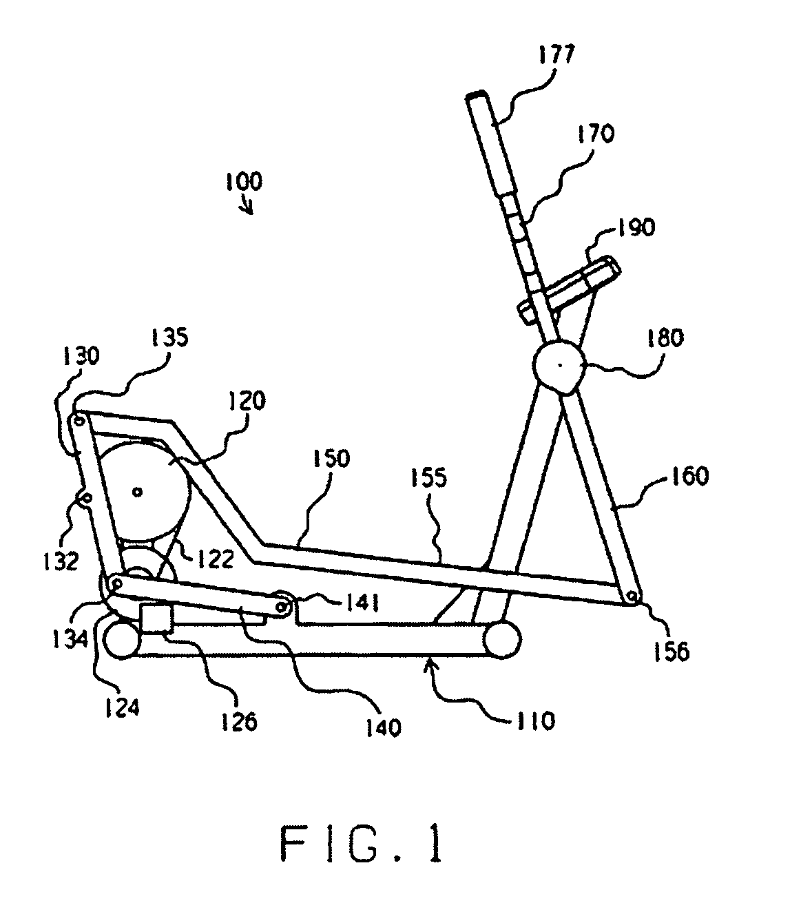
[0006]The present invention provides unique methods and exercise apparatuses for total body exercise. In one sense, the present invention may be described as encouraging one or more arm-supporting members to be generally synchronized relative to respective leg-supporting member(s) while allowing relative movement between the arm-supporting members and respective leg-supporting members in response to the application of user forces. The present invention may also be said to encourage one or more arm-supporting members to be synchronized relative to respective leg-supporting members while subjecting the arm-supporting members to resistance applied and / or measured independent of the leg-supporting members.
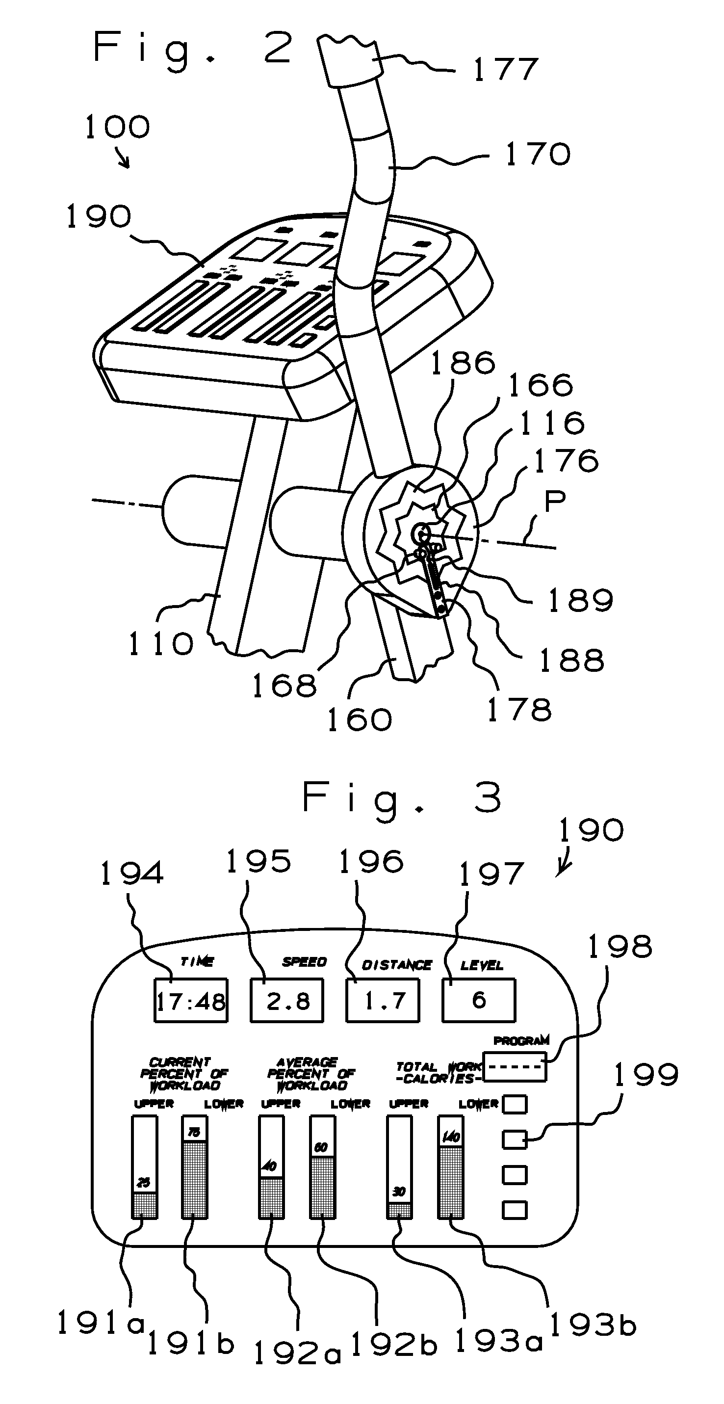
[0010]The preferred embodiment also includes a resistance device providing adjustable resistance to movement of the leg-supporting members and the arm-supporting members, and sensors for detecting user force exerted against respective arm-supporting members. In one desired mode of operation, resistance to movement of the leg-supporting members is set, and the resistance is subsequently adjusted as a function of user force applied against the arm-supporting members. As a result, upper body work can increase or decrease without affecting the amount of lower body work being performed by the user. Alternative embodiments of the present invention may be implemented with this “responsive resistance” arrangement to the exclusion of the resilient members discussed in the preceding paragraph, or with the resilient members to the exclusion of the “responsive resistance” arrangement.

Problems solved by technology

Synchronized motion makes the equipment relatively easy to use but the perceived quality of exercise tends to exceed the actual quality of exercise because the arms typically perform very little work.
One notable example is the NordicTrack ski exercise apparatus (U.S. Pat. No. 4,728,102) but many people consider such exercise apparatuses relatively difficult to use, due to the independent nature of the arm motions and the leg motions.

Method used


Image

  • Adjustable stride length exercise method and apparatus
  • Adjustable stride length exercise method and apparatus
  • Adjustable stride length exercise method and apparatus

Examples


embodiment 100

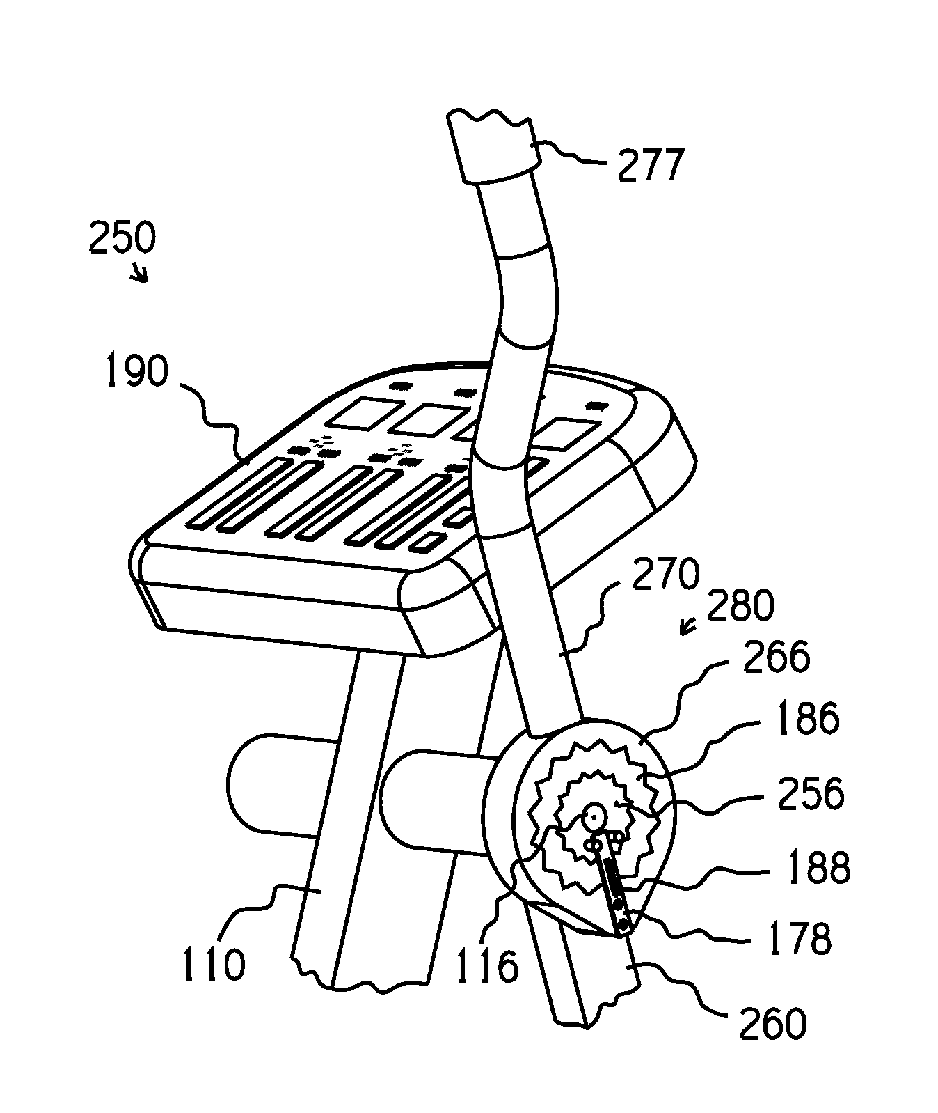
[0060]Generally speaking, the arrangement inside each cover 180 biases a respective arm-supporting member 170 to remain in a particular orientation relative to a respective rocker link 160. As a result, each arm-supporting member 170 will simply pivot together with a respective rocker link 160 (entirely “in sync”) when a user of exercise apparatus 100 is exercising his lower body to the exclusion of his upper body. However, when the user applies force through either arm-supporting member 170, the respective resilient member 186 will accommodate some pivoting or “flexing” of the arm-supporting member 170 relative to the respective rocker link 160. The freedom to move the arm-supporting member 170 out of sync, although limited in range, tends to provide the user with the sensation of having accomplished something with his upper body independent of the motion associated with exercise of his lower body. In other words, the user can increase the arm exercise stroke relative to the leg ex...

embodiment 300

[0073]An upper end 365 of each rocker link 360 is configured to provide an arcuate slot 367 which is centered about a respective pivot axis R. A respective block 385 is movably mounted within each slot 367, and is rigidly secured to an intermediate portion of a respective arm-supporting member 370 (by means of a bolt 375, for example). First and second resilient members 387 are preferably disposed in respective gaps defined between opposite sides of the block 385 and opposite ends of the slot 367 to bias the arm-supporting member 370 toward an aligned orientation relative to the rocker link 360. On this embodiment 300, the resilient members 387 are helical coil springs.

[0074]In the absence of user force applied against the arm-supporting members 370, the arm-supporting members 370 pivot in synchronized fashion together with respective rocker links 360. However, the resilient members 387 allow the arm-supporting members 370 to be forcibly moved relative to respective rocker links 360...

embodiment 15

[0102]As shown in FIG. 15, rotation of the flywheel 34 is linked to movement of the foot receiving member 42 through a generally elliptical path of motion P, and movement of the hand receiving member 72 through an arcuate path of motion Q. For example: (i) when the eccentric axis A is at seven o'clock relative to the camshaft axis Z, the foot receiving member 42 and the hand receiving member 72 occupy the positions shown in solid lines; (ii) when the eccentric axis is at the ten o'clock orientation (designated as Aa), the foot receiving member and the hand receiving member occupy the positions designated as 42a and 72a (and the user is likely to begin pushing against the hand receiving element); (iii) when the eccentric axis is at the one o'clock orientation (designated as Ab), the foot receiving member and the hand receiving member occupy the positions designated as 42b and 72b; and (iv) when the eccentric axis is at the four o'clock orientation (designated as Ac), the foot receivi...


PUM


Abstract

An exercise apparatus includes a frame for residing on a horizontal surface, a pair of arm-supporting members for supporting the user's arms and a pair of leg-supporting members for supporting the user's legs. A linkage assembly couples the arm-supporting members and leg-supporting members to the frame and moves the arm-supporting members and leg-supporting members in closed paths relative to the frame in response to user forces applied to the arm-supporting members and leg-supporting members. The linkage assembly includes actuators for adjusting dimensions of the closed paths in response to control signal inputs. Sensors mounted on the linkage assembly generate force-indicating signals representing one or more of the user force. A user interface receives and processes the force-indicating signals and supplies the control signal inputs to the actuators, wherein a dimension of at least one of the closed paths is a function of at least one of the forces applied to the leg and arm-supporting members.

Description

CROSS-REFERENCE TO RELATED APPLICATIONS[0001]This application is a continuation-in-part of U.S. patent application Ser. No. 11 / 482,232 filed on Jun. 30, 2006 (U.S. Pat. No. 7,604,574 issued Oct. 20, 2009), which is a continuation of U.S. patent application Ser. No. 09 / 065,308 filed on Apr. 23, 1998 (U.S. Pat. No. 7,086,993 issued Aug. 10, 2006). This application is also a continuation-in-part of U.S. patent application Ser. No. 10 / 712,784 filed on Nov. 12, 2003, now U.S. Pat. No. 7,556,589 which is a continuation-in-part of U.S. patent application Ser. No. 09 / 684,667 filed Oct. 6, 2000 (U.S. patent No. 6,672,994 issued Jan. 6, 2004).BACKGROUND OF THE INVENTION[0002]1. Field of the Invention[0003]The present invention relates to an exercise apparatus having arm and leg supporting members that travel in closed paths, and more specifically to an exercise apparatus that senses user forces applied to the exercise apparatus and automatically adjusts dimensions of the closed paths in respo...

Claims


Application Information

Patent Timeline
Patent Type & Authority Patents(United States)
IPC IPC(8): A63B69/16A63B22/04
CPCA63B21/0051A63B21/0083A63B21/012A63B21/225A63B22/0012A63B22/0056A63B22/0664A63B23/03525A63B24/0062A63B24/0075A63B2022/067A63B2022/0682A63B2024/0068A63B2071/0627A63B2071/0655A63B2208/0204A63B2208/0238A63B2220/20A63B2220/30A63B2225/15A63B2225/20A63B2230/06A63B2230/75A63B22/0017A63B21/023A63B2071/0063A63B21/00069A63B24/0087
Inventor MARESH, JOSEPH D.STEARNS, KENNETH W.
Owner MARESH JOSEPH D
Why Eureka
Try Eureka