

Adjustable stride length exercise method and apparatus
a stride length and adjustable technology, applied in the direction of gymnastic exercise, sport apparatus, frictional force resistor, etc., can solve the problems of perceived quality of exercise exceeding actual quality of exercise, and relatively difficult use of exercise apparatus
- Summary
- Abstract
- Description
- Claims
- Application Information
AI Technical Summary
Benefits of technology
Problems solved by technology
Method used
Image

Examples
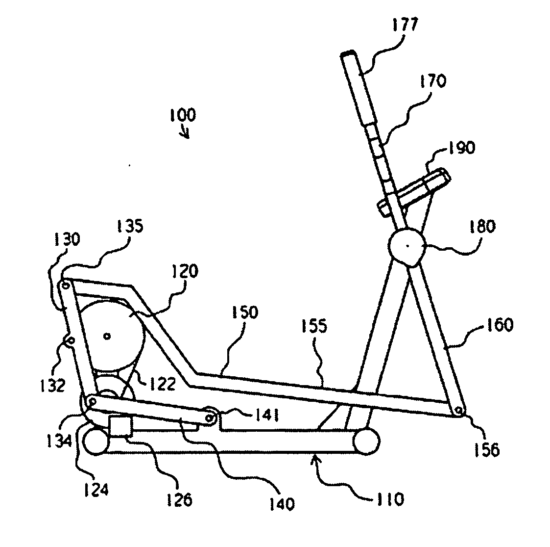
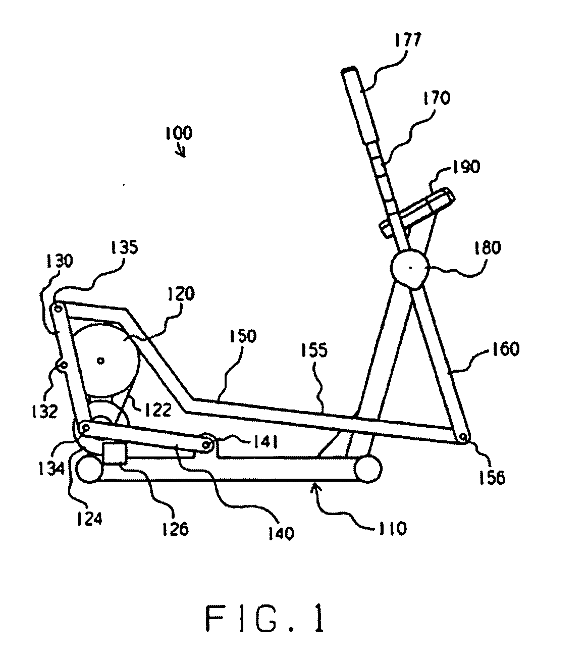
embodiment 100
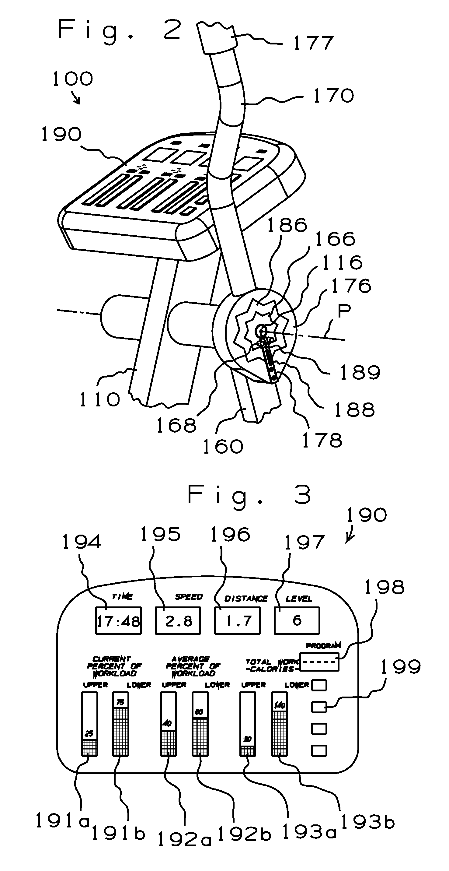
[0060]Generally speaking, the arrangement inside each cover 180 biases a respective arm-supporting member 170 to remain in a particular orientation relative to a respective rocker link 160. As a result, each arm-supporting member 170 will simply pivot together with a respective rocker link 160 (entirely “in sync”) when a user of exercise apparatus 100 is exercising his lower body to the exclusion of his upper body. However, when the user applies force through either arm-supporting member 170, the respective resilient member 186 will accommodate some pivoting or “flexing” of the arm-supporting member 170 relative to the respective rocker link 160. The freedom to move the arm-supporting member 170 out of sync, although limited in range, tends to provide the user with the sensation of having accomplished something with his upper body independent of the motion associated with exercise of his lower body. In other words, the user can increase the arm exercise stroke relative to the leg ex...
embodiment 300
[0073]An upper end 365 of each rocker link 360 is configured to provide an arcuate slot 367 which is centered about a respective pivot axis R. A respective block 385 is movably mounted within each slot 367, and is rigidly secured to an intermediate portion of a respective arm-supporting member 370 (by means of a bolt 375, for example). First and second resilient members 387 are preferably disposed in respective gaps defined between opposite sides of the block 385 and opposite ends of the slot 367 to bias the arm-supporting member 370 toward an aligned orientation relative to the rocker link 360. On this embodiment 300, the resilient members 387 are helical coil springs.
[0074]In the absence of user force applied against the arm-supporting members 370, the arm-supporting members 370 pivot in synchronized fashion together with respective rocker links 360. However, the resilient members 387 allow the arm-supporting members 370 to be forcibly moved relative to respective rocker links 360...
embodiment 15
[0102]As shown in FIG. 15, rotation of the flywheel 34 is linked to movement of the foot receiving member 42 through a generally elliptical path of motion P, and movement of the hand receiving member 72 through an arcuate path of motion Q. For example: (i) when the eccentric axis A is at seven o'clock relative to the camshaft axis Z, the foot receiving member 42 and the hand receiving member 72 occupy the positions shown in solid lines; (ii) when the eccentric axis is at the ten o'clock orientation (designated as Aa), the foot receiving member and the hand receiving member occupy the positions designated as 42a and 72a (and the user is likely to begin pushing against the hand receiving element); (iii) when the eccentric axis is at the one o'clock orientation (designated as Ab), the foot receiving member and the hand receiving member occupy the positions designated as 42b and 72b; and (iv) when the eccentric axis is at the four o'clock orientation (designated as Ac), the foot receivi...
PUM
 Abstract
Description
Claims
Application Information