

Full body twisting exercise machine
- Summary
- Abstract
- Description
- Claims
- Application Information
AI Technical Summary
Benefits of technology
Problems solved by technology
Method used
Image

Examples
Embodiment Construction
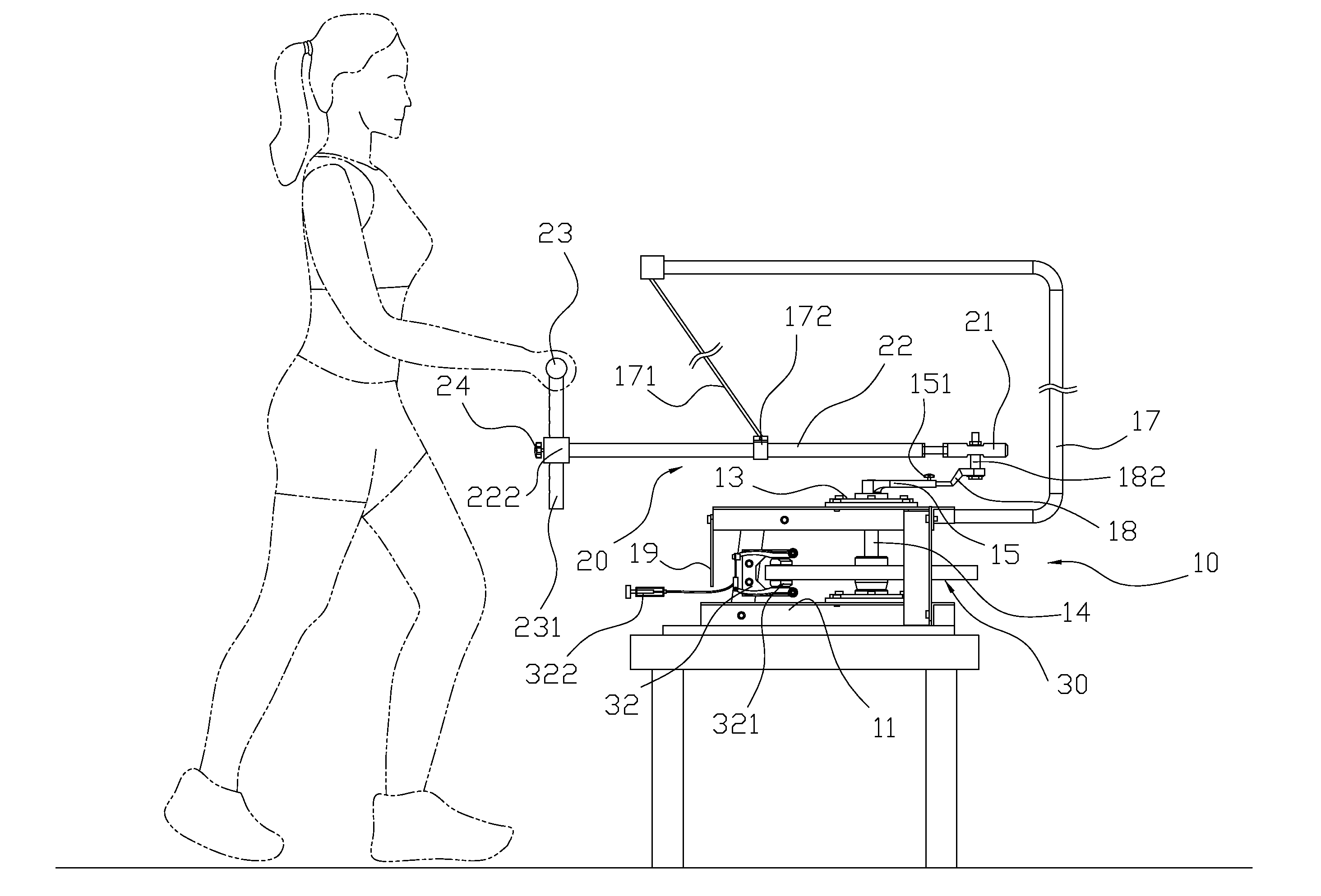
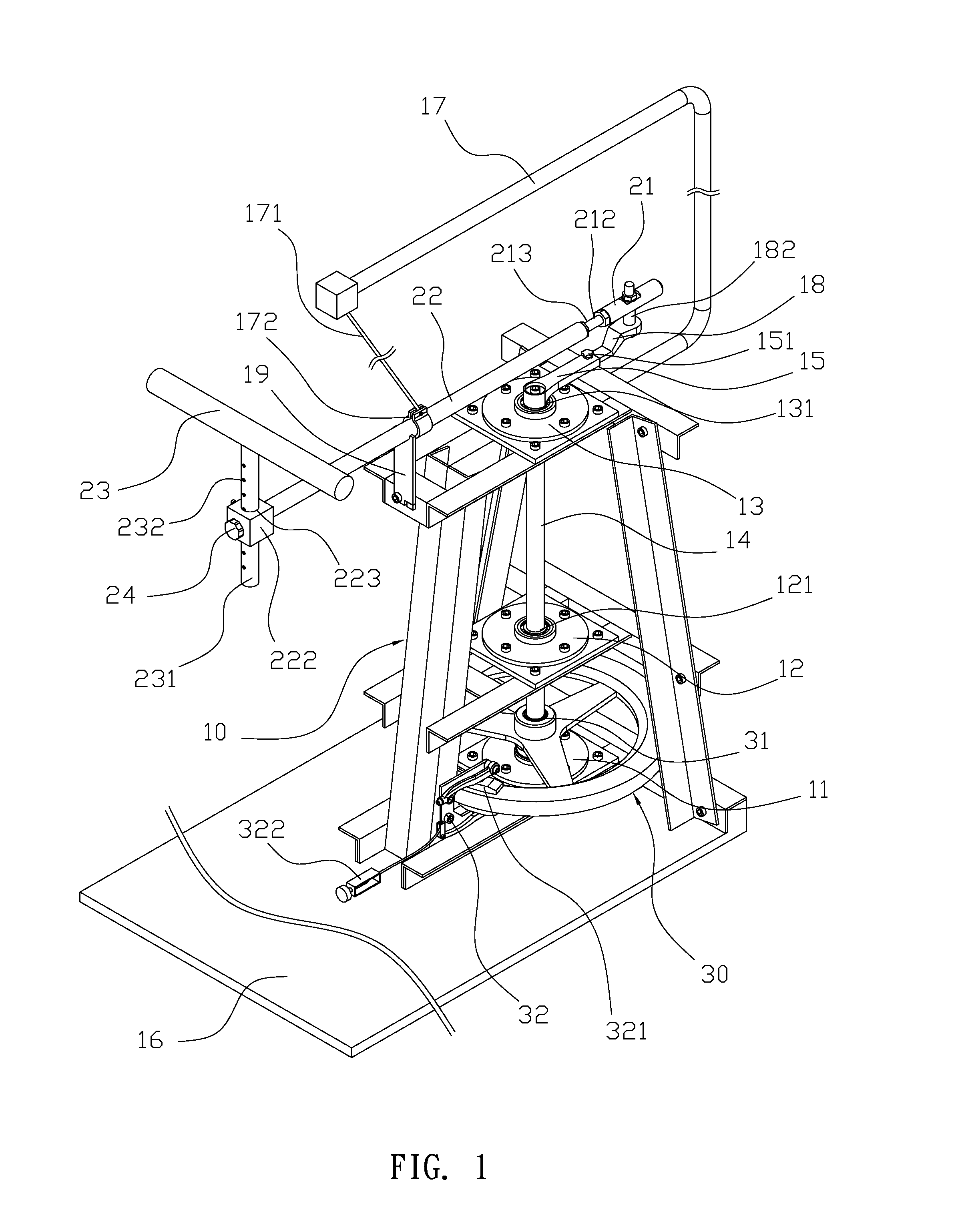
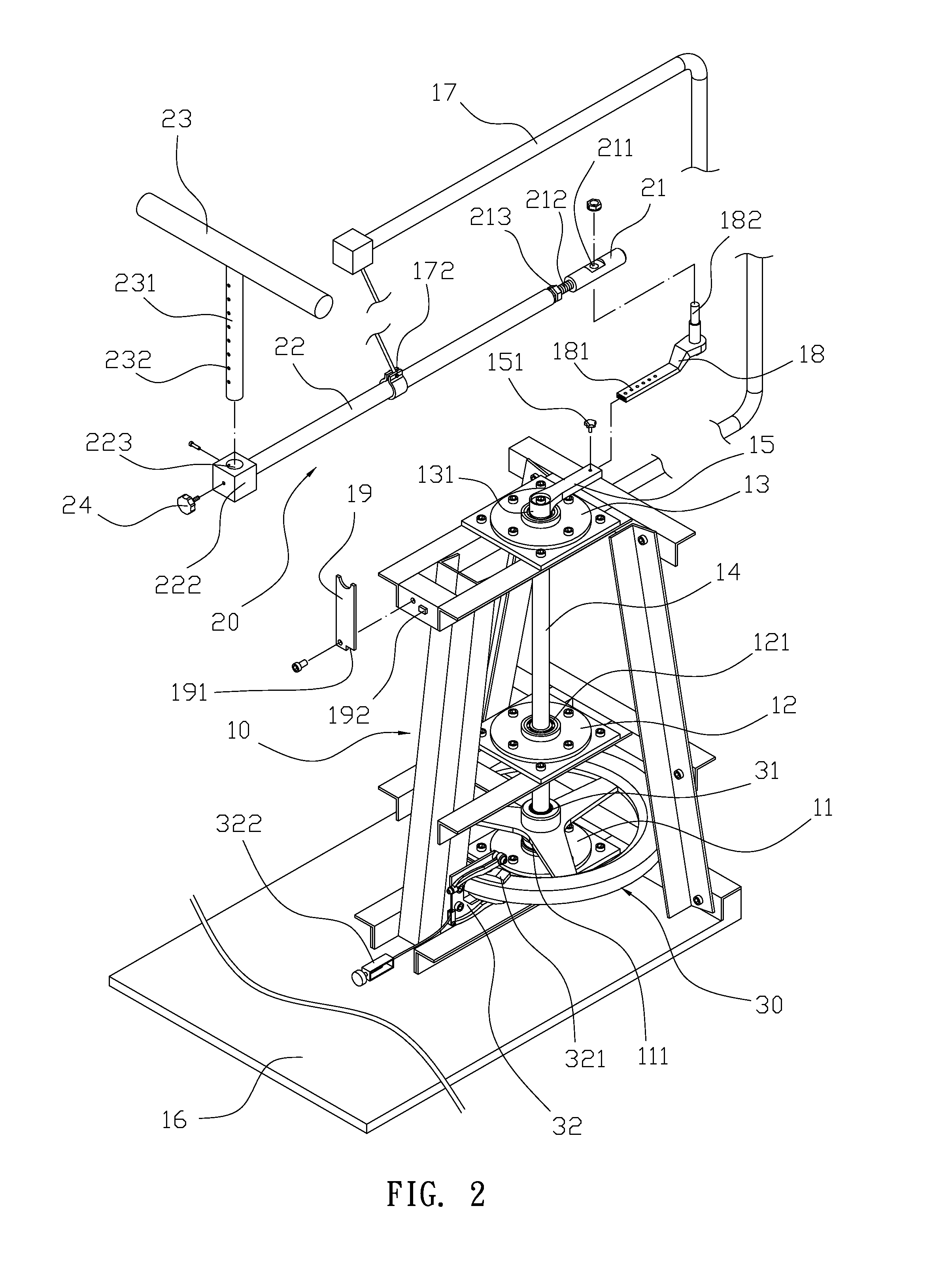
[0026]Please refer to FIG. 1, FIG. 2 and FIG. 3. A full body twisting exercise machine comprises a support frame 10, a control set 20 and a flywheel 30. The support frame 10 comprises a lower layer portion 11 and an upper layer portion 13; bearings 111, 131 are respectively installed at the lower and the upper layer portions 11, 13. A revolving shaft 14 is vertically disposed though both bearings 111, 131. The support frame 10 further comprises a middle layer portion 12 between the lower and the upper layer portions 11, 13, and a bearing 121 is installed at the middle layer portion 12 and jackets the revolving shaft 14 to increase the rotational stability of the revolving shaft 14. One end of the revolving shaft 14 protrudes from the upper layer portion 13 and is connected to a crank 15. The crank 15 further comprises an extension bar 18 inserted thereof and a positioning knob 151 at an end, and the extension bar 18 provides a plurality of adjustment apertures 181 providing differen...
PUM
 Abstract
Description
Claims
Application Information