Implantable transducer for hearing aids and process for tuning the frequency response of one such transducer

Inactive Publication Date: 2005-02-15
SONOVA AG
View PDF11 Cites 9 Cited by
  • Summary
  • Abstract
  • Description
  • Claims
  • Application Information

AI Technical Summary

Benefits of technology

This defect is remedied in a simple and effective manner by the invention. By multiple use of individual components of the transducer, the amount of space required for the transducer is kept particularly small. Additionally, the number of required individual parts and installation cost are minimized.

Problems solved by technology

This is especially important in the case of implants since the supply of power supply is often a problem; such that what matters is converting a certain amount of electrical energy into the largest possible amount of mechanical energy.
One common requirement for implantable actuator and sensor transducers for hearing aids is miniaturization since the space which is available for implantation is generally extremely limited.
In currently available concepts for implantable transducers, there are no mechanisms which make it possible to systematically tune the frequency response of the same actuator matched to the conditions which can be expected at the implantation site.

Method used


Image

  • Implantable transducer for hearing aids and process for tuning the frequency response of one such transducer
  • Implantable transducer for hearing aids and process for tuning the frequency response of one such transducer
  • Implantable transducer for hearing aids and process for tuning the frequency response of one such transducer

Examples


Embodiment Construction

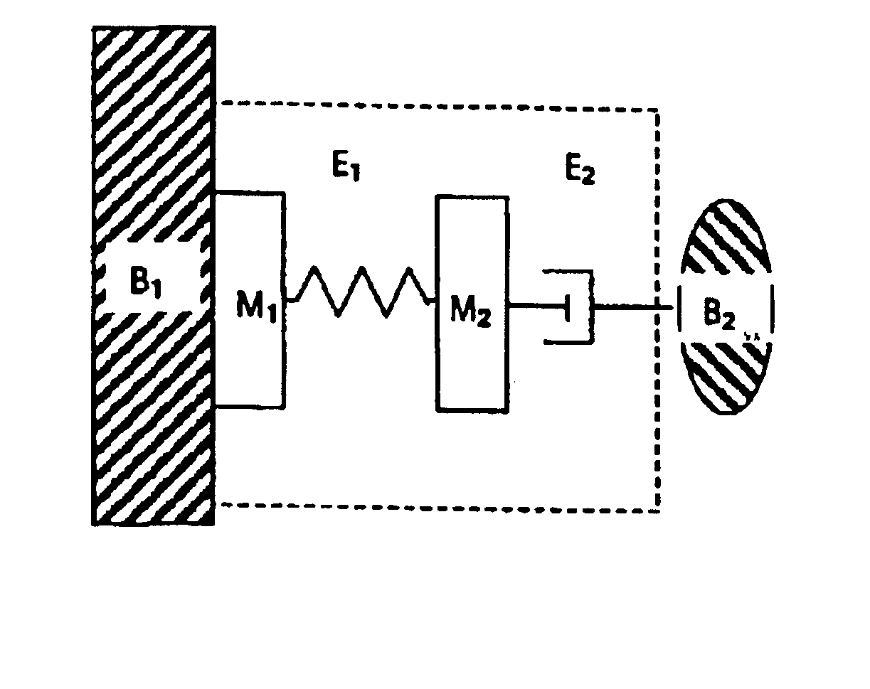
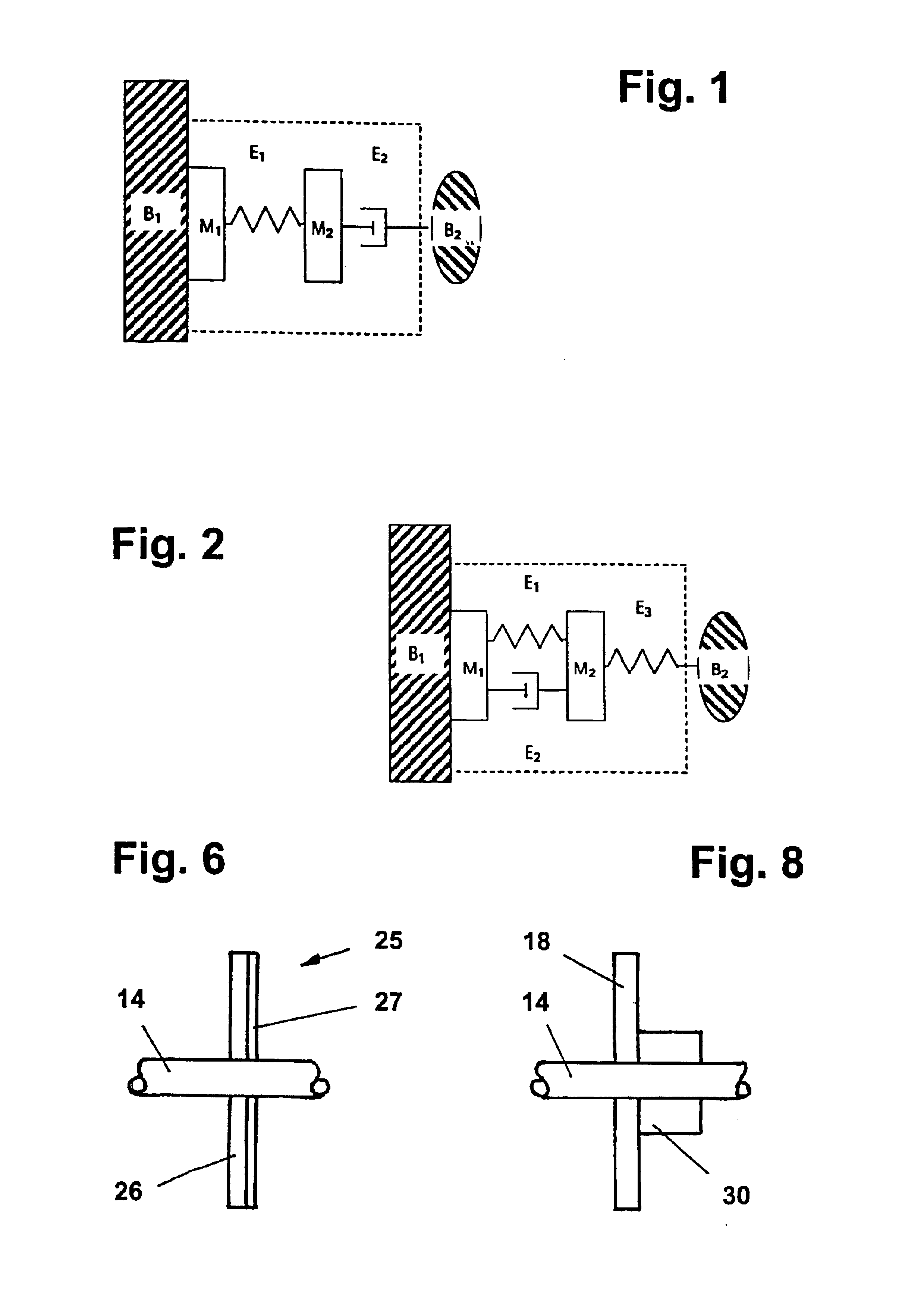
The schematics of FIGS. 1 and 2 show, in the block which is framed by the broken lines, a transducer which can be selectively used as an actuator which excites vibrations or a sensor which detects vibrations. M1 is the static part of the transducer. The static transducer part M1 represents an element which in the implanted state is in essentially rigid contact with a body part B1 of the implant wearer, for example, a muscle or bone which has a large mass compared to the mass of the transducer. M2 in FIGS. 1 and 2 represents the dynamic part of the transducer. M2 is in contact with a body part B2 of the implant wearer; its mass or impedance is preferably comparable to the mass or impedance of the transducer. Body part B2 can be the eardrum, a middle ear ossicle, the perilymph or the basilar membrane in the inner ear, especially in the case of an actuator.

In the arrangement shown in FIG. 1, the static transducer part M1 and the dynamic transducer part M2 are mechanically connected to ...


PUM


Abstract

An implantable electromagnetic transducer for hearing aids and process for tuning its frequency response are disclosed. The transducer is provided with a static transducer part which includes a hermetically sealed transducer housing and a ring coil arrangement which is mounted inside, and with a dynamic part which is mechanically connected to the static transducer part via at least one connecting element which is coupled in the implanted state to part of the body of the implant wearer via at least one connecting element. The implantable transducer has a permanent magnet arrangement, which interacts with the ring coil arrangement and which is supported to be able to vibrate by means of a support in the direction of the axis of the ring coil arrangement, with at least one connecting element being made as a multifunction element which is part of the support and / or part of the hermetically tight transducer housing. The mechanical properties of the multifunction element are selected for achieving a set frequency response of the transducer.

Description

BACKGROUND OF THE INVENTION1. Field of the InventionThe invention relates to an implantable transducer for hearing aids which transducer operates using the electromagnetic transducer principle, and to a process for tuning the frequency response of the transducer.2. Description of Related ArtTransducers of this type are known fundamentally, for example, from HNO, 1997-45:792-800, H. Leysieffer et al. “An implantable piezoelectric hearing aid transducer for those suffering from labyrinthine deafness.” This article is concerned especially with piezoelectric transducers, it is, however, generally pointed out that actuator hearing aid transducers also can be implemented using the electromagnetic transducer process. That is, in such an electromagnetic transducer a permanent magnet moves in the field of a stationary coil, whose field changes in time, which has the advantage of a miniaturization capacity of the movable permanent magnet.One embodiment of an electromagnetic transducer which i...

Claims


Application Information

Patent Timeline
IPC IPC(8): H04R25/00H04R11/00
CPCH04R25/606H04R11/00
Inventor SCHMID, CHRISTOPHBERNHARD, HANSSTRUZKA, ZBYNEK
Owner SONOVA AG
Why Eureka
Try Eureka