Teeth cleaning brush structure

Inactive Publication Date: 2007-01-02
WELTERS
View PDF5 Cites 12 Cited by
  • Summary
  • Abstract
  • Description
  • Claims
  • Application Information

AI Technical Summary

Benefits of technology

[0004]It is, therefore, the primary purpose of the present invention to provide a teeth cleaning brush structure, comprising a cleaning brush, a cover, a stick sleeve, a cleaning rod, and a control means wherein the cleaning rod has a coupling section extending at one end thereof for the control means to be pivotally joined thereto via a pivot section; whereby, the control means is bent upwards in a straight angle to reveal a transverse through hole for the cleaning brush to be adapted thereto, and then rotated downwards to locate the cleaning brush in clamping abutment therein for use, providing a portable cleaning brush which is assembled or replaced in an easy and fast manner without any other tools required.
[0005]It is, therefore, the secondary purpose of the present invention to provide a teeth cleaning brush structure wherein, via the control means pivotally joined to the cleaning rod thereof, the cleaning brush can be pivotally rotated to adjust the angle of the bristles so as to suitably apply the bristles to the teeth in cleaning, achieving more efficient cleaning effect of the cleaning brush thereof

Problems solved by technology

When going outside, one can only use dental floss or toothpicks 10 to simply clean the teeth; which, however, can't efficiently clear the remains of food or tartar on teeth.
Thus, neither a simple nor a combined use of the conventional teeth cleaning tools can completely meet the need of users in cleaning teeth.
With the bristles 22 fixedly attached to the cleaning brush 20 thereof, the cleaning brush 20 must be discarded altogether once the bristles 22 are worn out of use, which is not only uneconomical but also increase the burden of the environment.

Method used


Image

  • Teeth cleaning brush structure
  • Teeth cleaning brush structure
  • Teeth cleaning brush structure

Examples


Embodiment Construction

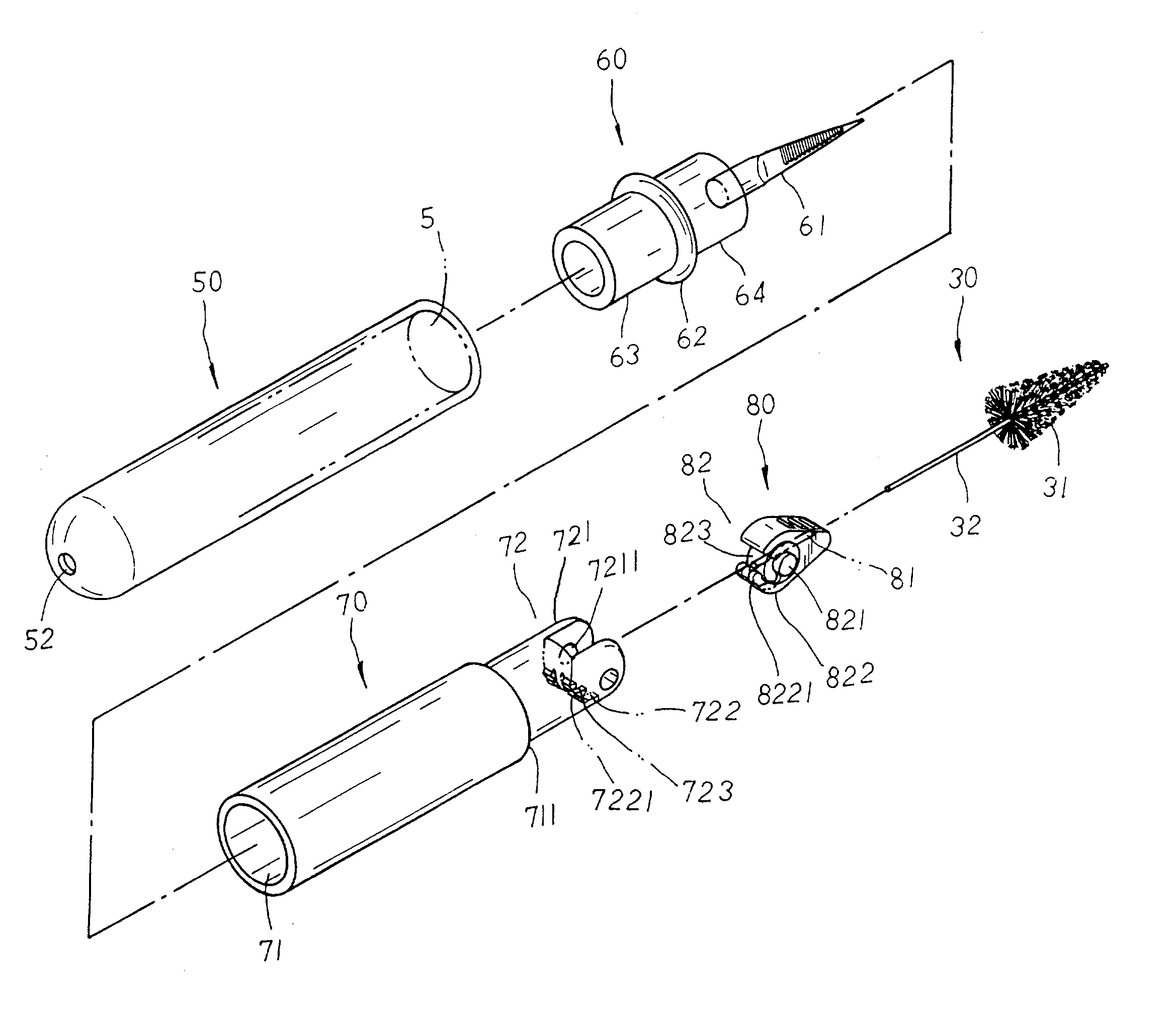
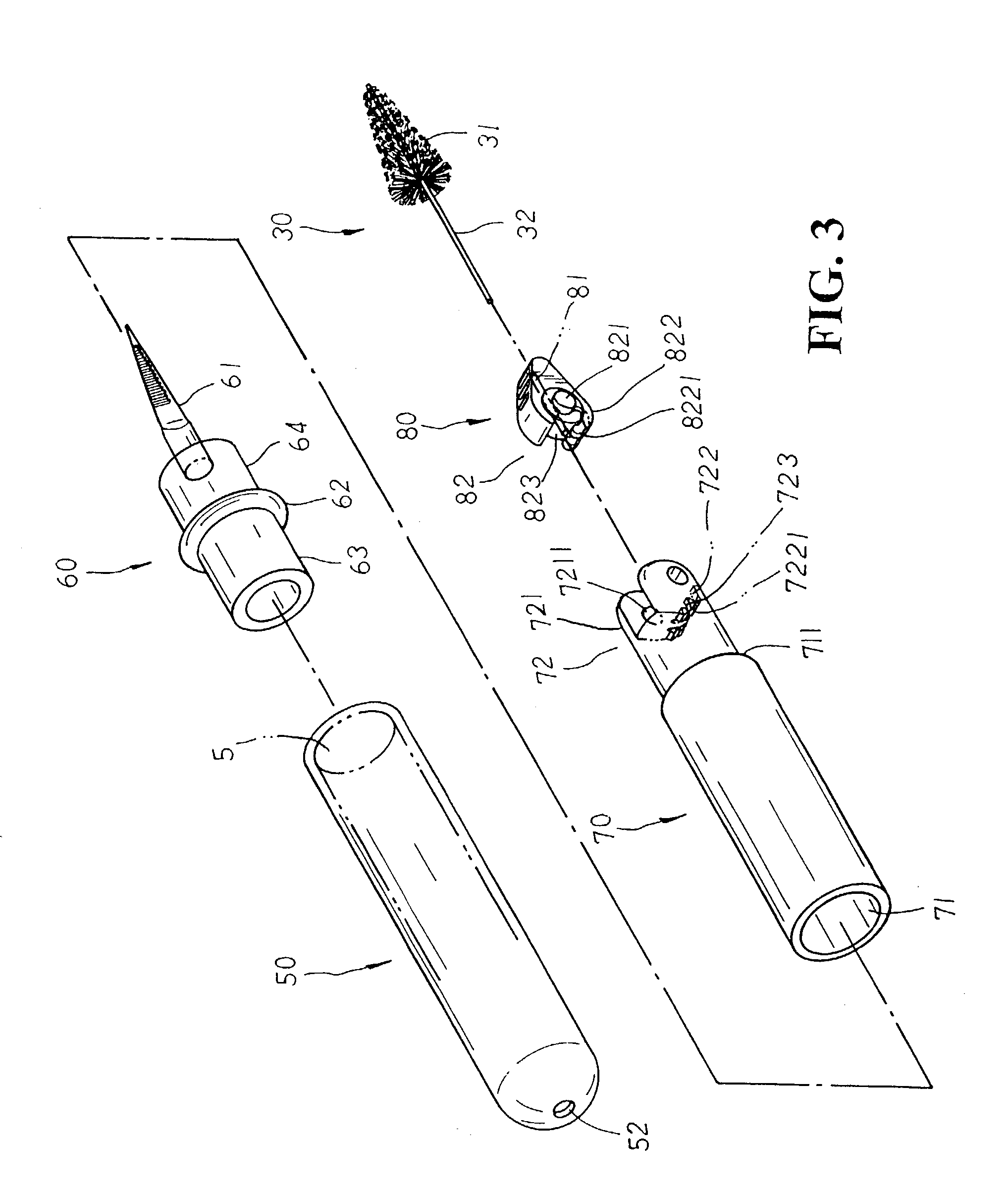
[0013]Please refer to FIG. 3. The present invention is related to a teeth cleaning brush structure, comprising a cleaning brush 30, a cover 50, a stick sleeve 60, a cleaning rod 70, and a control means 80. The cleaning brush 30 is made up of bristles 31 winding in tapered circles at one end thereof, and a flexible insert rod 32 extending for a certain length at the bottom of the bristles 31 thereof. The cover 50 has an open receiving groove 51 disposed at one end thereof, and an air hole 52 disposed at the other closed end thereof. The stick sleeve 60 is provided with a cleaning stick 61 disposed at one end thereof, a stop ring 62 projecting at the middle of the other end thereof, and a left and a right sleeve parts 63, 64 disposed at both sides of the stop ring 62 thereof. The cleaning rod 70 has a hollow retaining chamber 71 disposed at one end thereof, a stop step flange 711 defining the other end thereof, and a coupling section 72 extending at one side of the stop step flange 71...


PUM


Abstract

A teeth cleaning brush structure including a cleaning brush, a cover, a stick sleeve, a cleaning rod, and a control device. The cleaning brush has bristles and a flexible insert rod extending from an end of the bristles. The cover has an open receiving groove located at one end forth stick sleeve with a cleaning stick disposed at one end to be inserted. The cleaning is equipped with a hollow retaining chamber located at a first end and coupling section extending from a second end matching a pivot section of the control device. The control device is mounted to the coupling section of the cleaning rod via the pivot section. The flexible insert rod of the cleaning brush is inserted through a through hole of the control device, when the control device is pivoted upwardly and locked in position when the control device is rotated downwardly.

Description

BACKGROUND OF THE INVENTION[0001]The present invention is related to a teeth cleaning brush structure, comprising a cleaning brush, a cover, a stick sleeve, a cleaning rod, and a control means wherein the cleaning brush has bristles disposed at one end and a flexible insert rod extending at the other end thereof to be adapted to a transverse through hole of the control means. The cover has an open receiving groove disposed at one end thereof for the stick sleeve with a cleaning stick disposed at one end to be adapted thereto. The cleaning rod is equipped with a hollow retaining chamber disposed at one end thereof, and a coupling section extending at the other end thereof for the control means to be pivotally joined thereto via a pivot section; whereby, the cleaning brush is assembled or replaced in an easy and fast manner without any other tools required. Besides, the cleaning brush can also be pivotally rotated to adjust the angle of the bristles suitably to the teeth in cleaning, ...

Claims


Application Information

Patent Timeline
IPC IPC(8): A45D44/18A46B3/18A46B9/04A46B15/00
CPCA46B3/18A61C15/00A46B15/0055A46B2200/108
Inventor HSU, WALTER
Owner WELTERS
Why Eureka
Try Eureka