Finishing device

a finishing device and finishing technology, applied in the direction of grinding/polishing apparatus, grinding machines, manufacturing tools, etc., can solve the problems of reducing the workpiece deflection, and consuming a considerable amount of time and effort. , to achieve the effect of improving the finishing device, reducing the overall machining time, and eliminating the deflection of the workpi

Active Publication Date: 2018-06-05
SUPFINA GRIESHABER GMBH & CO KG
View PDF30 Cites 0 Cited by
  • Summary
  • Abstract
  • Description
  • Claims
  • Application Information

AI Technical Summary

Benefits of technology

[0010]The finishing device according to the invention provides for a concept which is tilted by an angle of 90° with respect to conventional finishing devices known from prior art. The new concept provides for a very small footprint of the finishing device which thus occupies a small shop floor area only. Further, the vertical machine concept has the advantage that parts of the finishing device are easily accessible such that the finishing device according to the invention can be set up in a fast and easy manner such that preparing the finishing device for finishing workpieces of a medium or small batch will take less time compared to conventional horizontal machine concepts.
[0030]Finally, it is contemplated that a machine housing is provided, the machine housing including housing parts which are moveable between a working position and a maintenance position, wherein a drive for moving the housing parts is provided. Such a machine housing protects the environment and operators from parts of a finishing device which are moving during operation, keeps cooling liquid within the machine housing but at the same time enables an operator to easily access parts of the finishing device in order to maintain them or in order to set them up for a different batch of workpieces.

Problems solved by technology

When used for large-scale production, for example when finishing the crankshaft of a four-cylinder engine commonly used in a great number of vehicles, setting up a finishing device may consume a considerable amount of time and effort which then is compensated for by an extended operation time of the device.
Such a compensation is difficult or impossible to achieve when using the finishing method for medium and small batch production, thus making this method comparatively expensive.

Method used


Image

  • Finishing device
  • Finishing device
  • Finishing device

Examples


Embodiment Construction

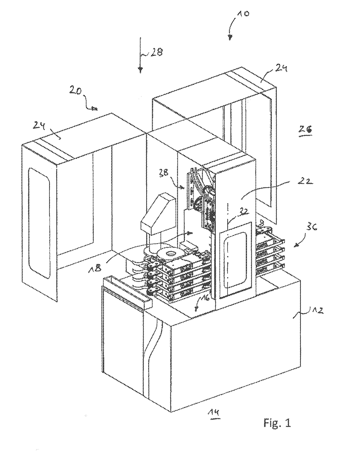
[0041]In the drawings, reference sign 10 designates a machine tool in the form of a finishing device. The device 10 includes a machine frame 12 which is set up on a floor 14 and has a horizontal upper surface 16 delimiting the lower end of a workspace 18.

[0042]The workspace 18 is further limited towards the sides and towards the top by means of a machine housing 20. The housing 20 may include stationary housing elements 22 and movable housing parts 24. The movable housing parts 24 may be positioned in a maintenance position (FIG. 1) allowing for an easy access to the workspace 18. The movable housing parts 24 may also be positioned in a working position, in which the housing parts delimit a box-shaped workspace 18 and provide protection for an environment 26 of the device 10. For moving the housing parts 24, they may be mounted in a pivotable manner and handled manually or driven by means of a drive which may for example be electric.

[0043]When using the expressions “horizontal” and ...


PUM


Abstract

A finishing device includes a finishing belt, a finishing belt holding device, a first drive configured to rotationally drive a workpiece about a workpiece axis, and a second drive configured to oscillate the workpiece and the finishing belt relative to another along the workpiece axis. The finishing belt holding device has a holding section configured to hold a portion of the finishing belt. The portion has an active area configured to finish a circumferential workpiece surface. The portion extends in a plane which is vertical when referring to the direction of gravity and extends in a horizontal direction when referring to the direction of gravity and when viewing in the running direction of the finishing belt. The finishing device includes a workpiece holding device defining a workpiece holding axis which is vertical when referring to the direction of gravity.

Description

TECHNICAL FIELD[0001]The present invention relates to a finishing device, including a finishing belt, a finishing belt holding device, a first drive for rotationally driving a workpiece about a workpiece axis and a second drive for oscillating the workpiece and the finishing belt relative to another along the workpiece axis.BACKGROUND OF THE INVENTION[0002]Finishing devices are also known as “shortstroke honing devices” and are described, e.g., in DE 10 2007 059 926 A1 (corresponding to US 2009 / 0142997 A1) and 44 23 422 A1.[0003]Such devices are used for the finish machining of circumferential surfaces of substantially rotationally symmetrical workpiece portions on workpieces, such as crankshafts or camshafts. Finishing is a precision machining method, in which the circumferential surfaces of substantially rotationally symmetrical workpiece portions on workpieces (such as main journals and pin journals of a crankshaft) are worked for producing a particularly smooth surface structure...

Claims


Application Information

Patent Timeline
Patent Type & Authority Patents(United States)
IPC IPC(8): B24B33/08B24B21/04B24B21/02B24B21/00B24B33/04B24B5/42B24B5/01B24B5/04
CPCB24B33/08B24B5/01B24B5/047B24B33/04B24B21/004B24B21/02B24B21/04B24B5/42
Inventor COELHO, STEPHEN
Owner SUPFINA GRIESHABER GMBH & CO KG
Why Eureka
Try Eureka