Apparatus for inserting or removing a clothing in an industrial machine

a technology of industrial machines and clothing, applied in the field of clothing accessories for inserting or removing clothing in industrial machines, can solve the problems of inability to accept web markings, large and also relatively heavy clothing, and relatively time-consuming clothing

Active Publication Date: 2013-11-05
VALMET TECH INC
View PDF14 Cites 0 Cited by
  • Summary
  • Abstract
  • Description
  • Claims
  • Application Information

AI Technical Summary

Benefits of technology

[0014]One objective of the invention is to provide an improved method and an improved system which do not display these drawbacks. Another objective of the invention is to provide a method and a system which enable operators to replace a clothing in an industrial machine, and in particular in a web forming or processing machine, in a fast and easy manner without having to risk damaging the clothing.

Problems solved by technology

The clothing can be wide and also relatively heavy.
Consequently, when such a clothing is used, a seam or a joint between the ends needs to be constructed, which is relatively time consuming.
Furthermore, seams or joints may cause unacceptable markings in the web.
However, when using this kind of sideways or cross direction (CD) replacement method the obvious problem arises of getting the clothing through the frame structure in which the support rolls are suspended.
Although cantilevering is a robust solution, it is desirable to find an alternative since its implementation is space consuming and also cost demanding.
Although the disclosed units do require very little space, the devices disclosed in WO 2006 / 106178 A1, WO 2008 / 129131 A1 and EP 2 063 023 A2 are relatively technically complicated and thus also expensive to fabricate.
This is, however, an unfavourable loading condition which may damage the clothing.

Method used


Image

  • Apparatus for inserting or removing a clothing in an industrial machine
  • Apparatus for inserting or removing a clothing in an industrial machine
  • Apparatus for inserting or removing a clothing in an industrial machine

Examples


Embodiment Construction

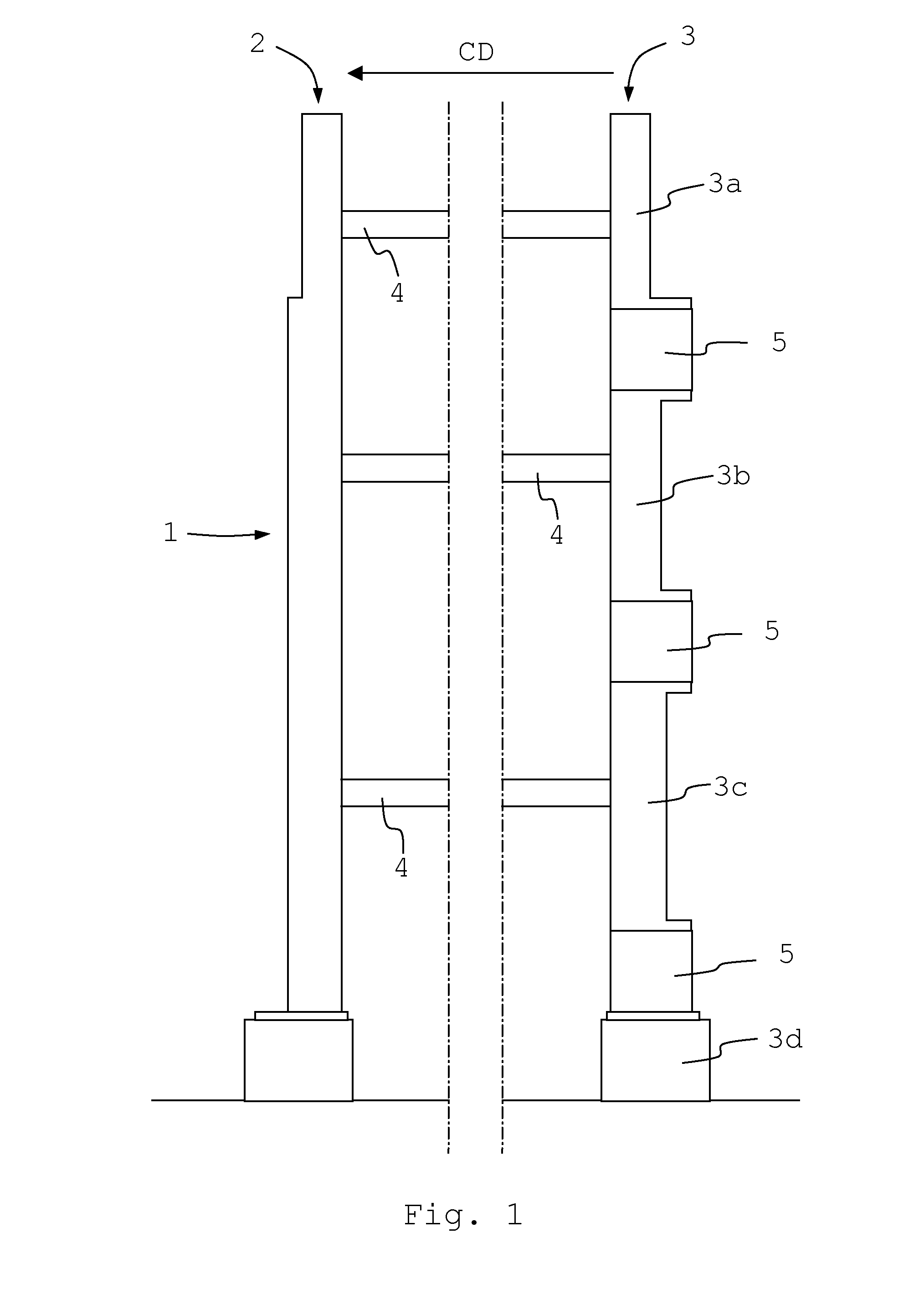
[0030]FIG. 1 is a cross-sectional view of a section of a frame structure 1 of a papermaking machine. The frame structure 1 is part of a processing section of the papermaking machine, e.g. a forming section or a press section. The frame structure 1 comprises a drive side vertical beam 2 and a tender side vertical beam 3. The frame structure 1 also comprises cross-directional, CD, horizontal beams 4 which run between the vertical beams 2 and 3.

[0031]Support rolls (not shown) are rotatably supported by the beams 2, 3 of the frame structure 1. Consequently, the beams 2, 3 act as carrier beams for the support rolls. The support rolls are arranged to guide or carry or otherwise support a flexible clothing (not shown in FIG. 1) in an endless loop as is well known in the art of papermaking. The clothing, in turn, is arranged to lead a web (not shown) through the processing section as is well known in the art of papermaking.

[0032]The vertical beam 3 on the tender side of the frame structure ...


PUM


Abstract

An apparatus (24) for inserting an endless, flexible clothing (15) in or removing such a clothing from an industrial machine in which the clothing is arranged to run in an endless loop, comprising first and second units (25, 26) between which the clothing is to be fed in an advancement direction (F) essentially transversal to the run direction of the clothing in the machine. According to the invention the apparatus comprises an upstream zone (A), an intermediate zone (B) and a downstream zone (C) along the advancement direction of the clothing; and also a member (29) for bringing the units to interact in the first zone and the third zone, alternately, such that the clothing is locked between the units in the first zone and the third zone, alternately, allowing the feeding of the clothing into the upstream zone when the clothing is locked between the units in the downstream zone such that the clothing is accumulated in the intermediate zone, and allowing the feeding of the clothing accumulated in the intermediate zone into the downstream zone when the clothing is locked between the units in the first zone such that the clothing is fed out of the apparatus through the downstream zone (C).

Description

CROSS REFERENCE TO RELATED APPLICATIONS[0001]This application is a national stage application filed under 35 U.S.C. 371 International Application No. PCT / SE2009 / 051337, filed Nov. 25, 2009, which claims priority to U.S. Provisional Application No. 61 / 258,884, filed Nov. 6, 2009, all of which are hereby Incorporated by reference in their entirety.BACKGROUND OF THE INVENTION[0002]The invention relates to an apparatus for inserting an endless, flexible clothing in or removing such a clothing from an industrial machine in which the clothing is arranged to run in an endless loop, comprising:[0003]a first structural unit and a second structural unit being arranged opposite to each other, said apparatus being arranged to feed the clothing between the first unit and the second unit in a clothing advancement direction essentially transversal to the run direction of the clothing in the machine.[0004]The invention also relates to an industrial machine comprising a flexible clothing running in ...

Claims


Application Information

Patent Timeline
Patent Type & Authority Patents(United States)
IPC IPC(8): D21F1/32
CPCD21F7/001
Inventor ANDERSSON, DANEKSTROM, GORAN
Owner VALMET TECH INC
Why Eureka
Try Eureka