Optical member and method of producing the same
- Summary
- Abstract
- Description
- Claims
- Application Information
AI Technical Summary
Benefits of technology
Problems solved by technology
Method used
Image
Examples
examples
[0073]The present invention will be described more specifically with reference to examples below, but is not limited to the examples. Each optical film having fine texture on the surface thereof prepared in each example or comparative example was evaluated by the following methods.
(1) Synthesis of Polyimides 1 to 10
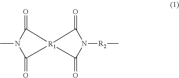
[0074]Diamine (1), diamine (2), and diamine (3) in a total amount of 0.012 mole were dissolved in N,N-dimethylacetamide (hereinafter, abbreviated as DMAc). To this diamine solution, 0.012 mole of an acid dianhydride was added while cooling the solution with water. The amount of DMAc was adjusted so that the total mass of the diamine and the acid dianhydride was 20% by weight. This solution was stirred at room temperature for 15 hr for polymerization. Then, the solution was diluted with DMAc to 8% by weight, and 7.4 mL of pyridine and 3.8 mL of acetic anhydride were added thereto, followed by stirring at room temperature for 1 hr and then in an oil bath with heating at 50°...
examples 1 to 4
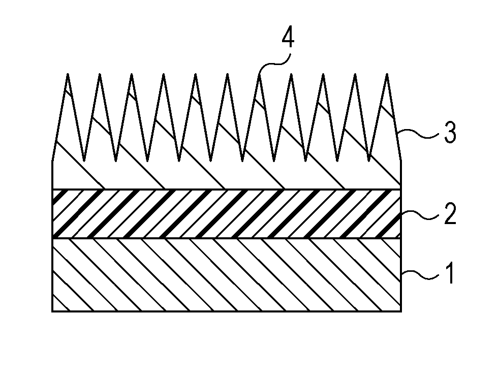
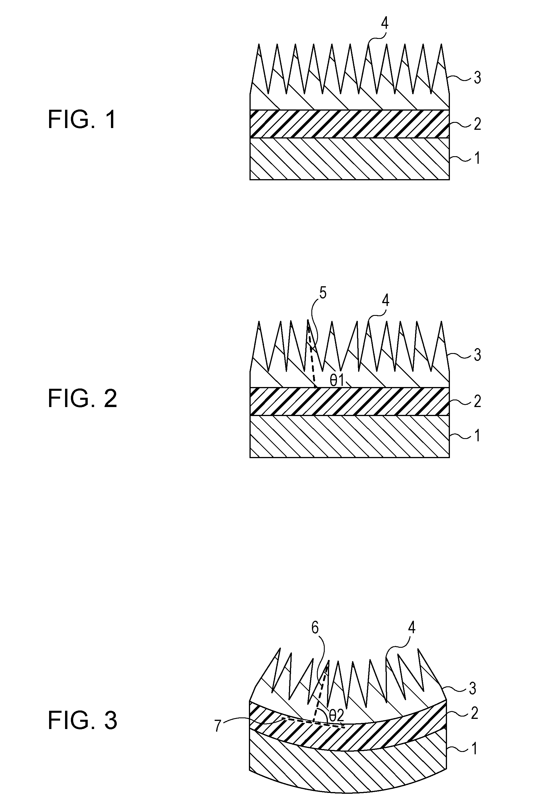
[0081]An appropriate amount of any of the polyimide solutions 1 to 4 was dropped onto the polished surface of a washed glass substrate A containing TiO2 as a main component and having nd=1.762 and νd=26.5, followed by spin coating at 4000 rpm. This substrate was dried at 200° C. for 60 min to provide the substrate with any of polyimide films where the polyimides 1 to 4 respectively represented by the following Formulae (8) to (11) were modified with 3-(triethoxysilyl)propyl isocyanate represented by the following Formula (12). The thickness and the refractive index of each of the polyimide films were measured with an ellipsometer.
[0082]An appropriate amount of an aluminum oxide precursor sol was dropped onto the polyimide film, followed by spin coating at 4000 rpm. The applied sol was baked in an oven with internal air circulation at 200° C. for 120 min to form an amorphous aluminum oxide coating on the polyimide film.
[0083]Then, the substrate was immersed in hot water of 75° C. for...
examples 5 to 9
[0086]The same process as that in Examples 1 to 4 was conducted using a washed glass substrate B containing TiO2 as a main component and having nd=1.847 and νd=23.8 instead of the glass substrate A and using polyimide solutions 5 to 9 instead of the polyimide solutions 1 to 4.
[0087]Thus, a polyimide film 5 where the polyimide 5 represented by the following Formula (13) was modified with 3-(triethoxysilyl)propyl isocyanate or 3-(trimethoxysilyl)propyl isocyanate represented by the following Formula (14) was formed on the glass substrate B. Though the type of the silane compound, its amount, and conditions for addition were different from those in Examples 1 to 4, no large differences were observed in the thickness and the refractive index of the polyimide film 5.
[0088]A plate crystal containing aluminum oxide as a main component was formed on the polyimide film 5 to provide the glass substrate with an antireflection film having an average reflectance of 0.07% to 0.1% at 400 to 700 nm...
PUM
| Property | Measurement | Unit |
|---|---|---|
| Fraction | aaaaa | aaaaa |
| Fraction | aaaaa | aaaaa |
| Percent by mass | aaaaa | aaaaa |
Abstract
Description
Claims
Application Information
 - R&D
- Intellectual Property
- Life Sciences
- Materials
- Tech Scout
- Unparalleled Data Quality
- Higher Quality Content
- 60% Fewer Hallucinations
Browse by: Latest US Patents, China's latest patents, Technical Efficacy Thesaurus, Application Domain, Technology Topic, Popular Technical Reports.
© 2025 PatSnap. All rights reserved.Legal|Privacy policy|Modern Slavery Act Transparency Statement|Sitemap|About US| Contact US: help@patsnap.com


