
Computer system, data migration method and storage management server

a data migration and computer system technology, applied in computing, electric digital data processing, instruments, etc., can solve the problems of prolonging the migration processing, not considering the execution sequence within the group in the data migration process, and complicated configuration of the computer system, so as to speed up the volume migration operation

Inactive Publication Date: 2010-11-09
HITACHI LTD
View PDF6 Cites 5 Cited by
  • Summary
  • Abstract
  • Description
  • Claims
  • Application Information

AI Technical Summary

Benefits of technology

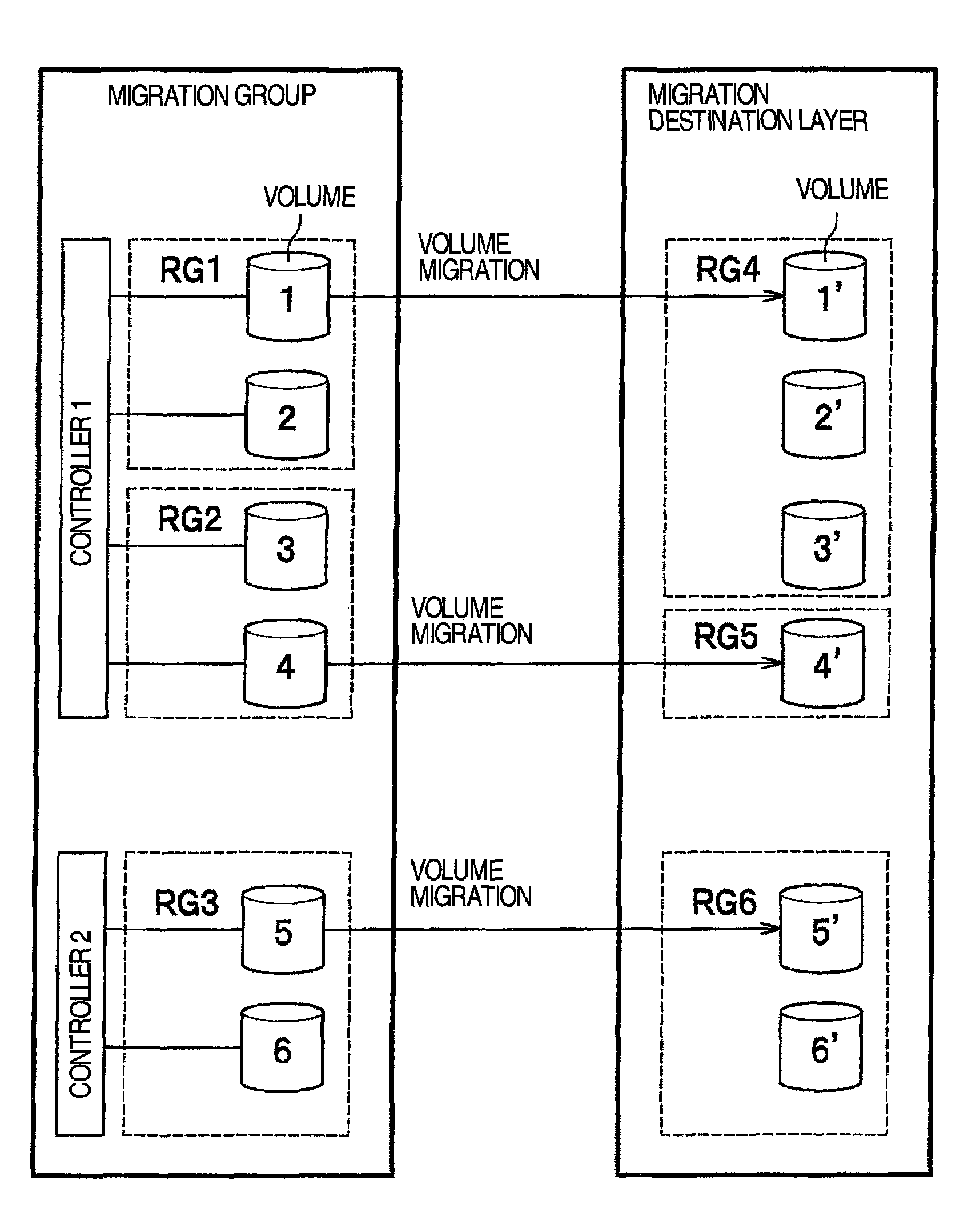
[0012]According to this invention, it is possible to avoid conflicting accesses to physical resources in the storage system and migrate (relocate) the volumes, speeding up the volume migration operation.

Problems solved by technology

An addition of a plurality of storage systems to a computer system as the amount of data to be managed increases results in the computer system becoming complicated in configuration.
The technology described in JP-A-2006-99748, however, does not consider an execution sequence within the group in the process of data migration.
Thus, if a plurality of volumes to be migrated share the same physical resources, such as physical disks and ports, there will be conflicting accesses to one location, prolonging the migration processing.

Method used


Image

  • Computer system, data migration method and storage management server
  • Computer system, data migration method and storage management server
  • Computer system, data migration method and storage management server

Examples


first embodiment

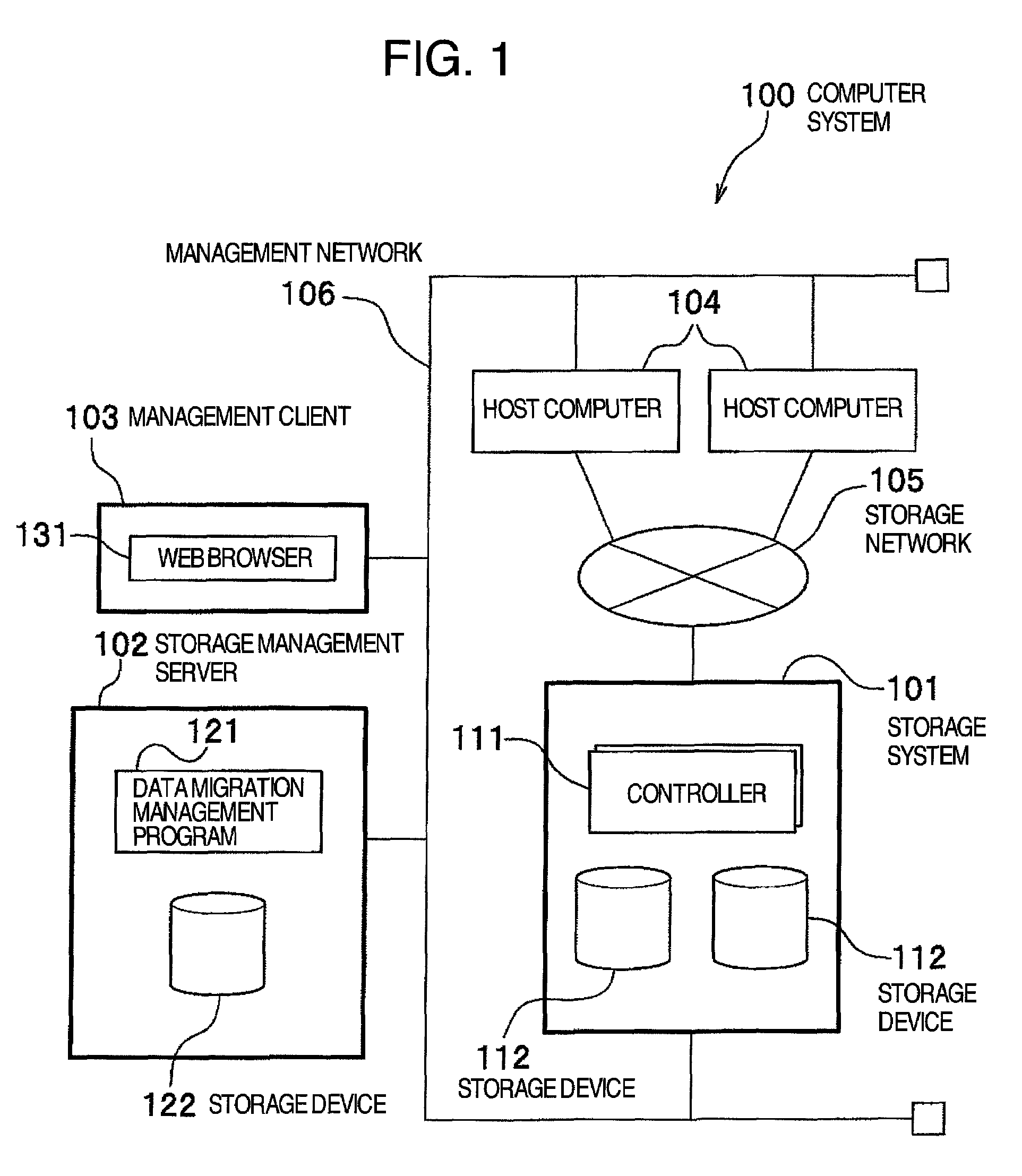
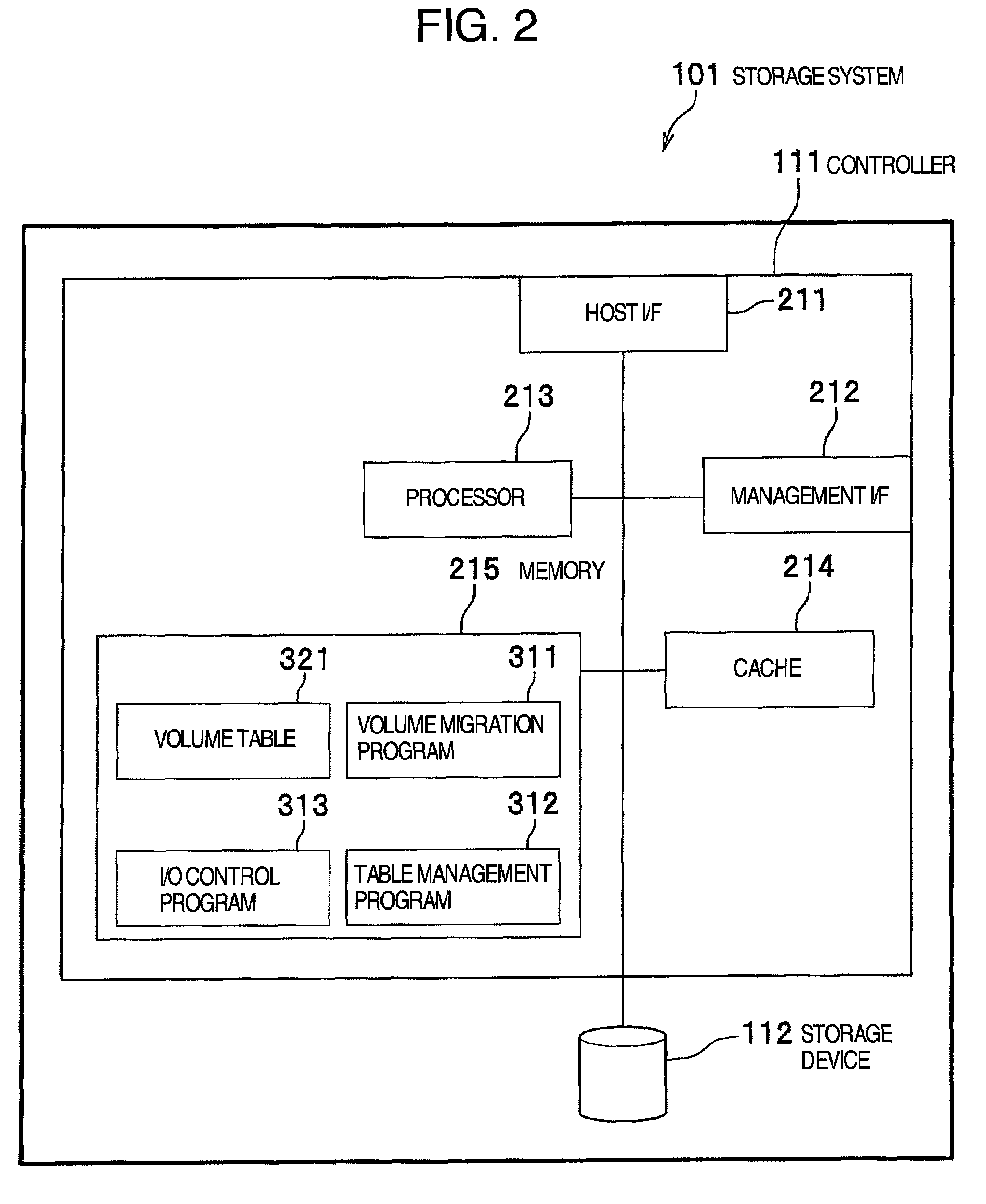
[0034]Referring to FIG. 1 through FIG. 3, detailed explanations will be given to the configuration of a computer system 100 according to the first embodiment.

[0035]FIG. 1 shows a hardware configuration of the computer system 100. The computer system 100 has a storage system 101, a storage management server 102, a management client 103, one or more host computers 104, a storage network 105 and a management network 106.

[0036]The host computer 104 may, for example, be a workstation system, a mainframe computer or a personal computer. The host computer 104 uses storage resources provided by the storage system 101 to execute a variety of jobs (e.g., database operations, Web application operations and streaming operations).

[0037]The storage network 105 interconnects one or more host computers 104 and the storage system 101. The storage network 105 may, for example, be a SAN (Storage Area Network), a LAN (Local Area Network), a WAN (Wide Area Network), the Internet, dedicated circuits and ...

second embodiment

[0145]A second embodiment is a construction in which the present invention is applied to the computer system that integrally manages a plurality of storage systems 101 by using a computer system virtualization technology. Those parts in this embodiment identical with the corresponding parts in the first embodiment are given like reference numbers and their duplicating explanations are omitted as appropriate.

[0146]FIG. 16 shows a hardware configuration of a computer system 100a in the second embodiment. A difference from the configuration of FIG. 1 is that the computer system 100a includes a plurality of storage systems 101 and that a virtualization device 107 is added. In the second embodiment, the host computers 104 connect to a plurality of storage systems 101 through the virtualization device 107 so that they can recognize storage resources (storage devices 112) of the plurality of storage systems 101 as logically one storage resource. The virtualization device 107 may, for examp...


PUM


Abstract

In a computer system an object of this invention is to reduce physical resource contentions during the parallel migration of volumes. The computer system of this invention has the host computers, the storage systems and the storage management server. When parallelly migrating two or more volumes of data in the storage systems to the same number of other volumes, the storage management server selects volumes having few physical conflicts of the controllers or storage devices in the storage systems and executes the parallel migration operation.

Description

INCORPORATION BY REFERENCE[0001]The present application claims priority from Japanese application JP2006-289406 filed on Oct. 25, 2006, the content of which is hereby incorporated by reference into this application.BACKGROUND OF THE INVENTION[0002]The present invention relates to a computer system to store a large amount of data and more particularly to a technology for migrating data.[0003]In recent years the amount of data handled by computer systems managed by corporations, local governments, government and municipal offices and financial institutions is increasing year by year. The increase in the amount of data is currently dealt with by adding new storage systems (storage devices) or migrating data among existing storage systems.[0004]An addition of a plurality of storage systems to a computer system as the amount of data to be managed increases results in the computer system becoming complicated in configuration. As one technology for solving this problem there is a virtualiz...

Claims


Application Information

Patent Timeline
Patent Type & Authority Patents(United States)
IPC IPC(8): G06F13/00G06F13/28
CPCG06F3/0613G06F3/0622G06F3/0647G06F3/067
Inventor MARUYAMA, TETSUYAASANO, MASAYASUYAMAMOTO, MASAYUKITAGUCHI, YUICHI
Owner HITACHI LTD
Learn More