Soil moisture sensor and controller

a moisture sensor and controller technology, applied in the field of moisture sensors, can solve problems such as unreliability of known capacitance based sensors

Active Publication Date: 2010-11-23
RAIN BIRD CORP
View PDF26 Cites 30 Cited by
  • Summary
  • Abstract
  • Description
  • Claims
  • Application Information

AI Technical Summary

Problems solved by technology

This is a problem when, for example, different zones have different soil types or are exposed to a different amount of sunlight or weather conditions than the soil in which the moisture sensor is located.
However, known capacitance based sensors operate unreliably and are influenced by factors such as variations in temperature and supply voltage.

Method used


Image

  • Soil moisture sensor and controller
  • Soil moisture sensor and controller
  • Soil moisture sensor and controller

Examples


Embodiment Construction

[0039]The following description is not to be taken in a limiting sense, but is made merely for the purpose of describing the general principles of the invention. The scope of the invention should be determined with reference to the claims. The present embodiments and examples address the problems described in the background while also addressing other additional problems as will be seen from the following detailed description.

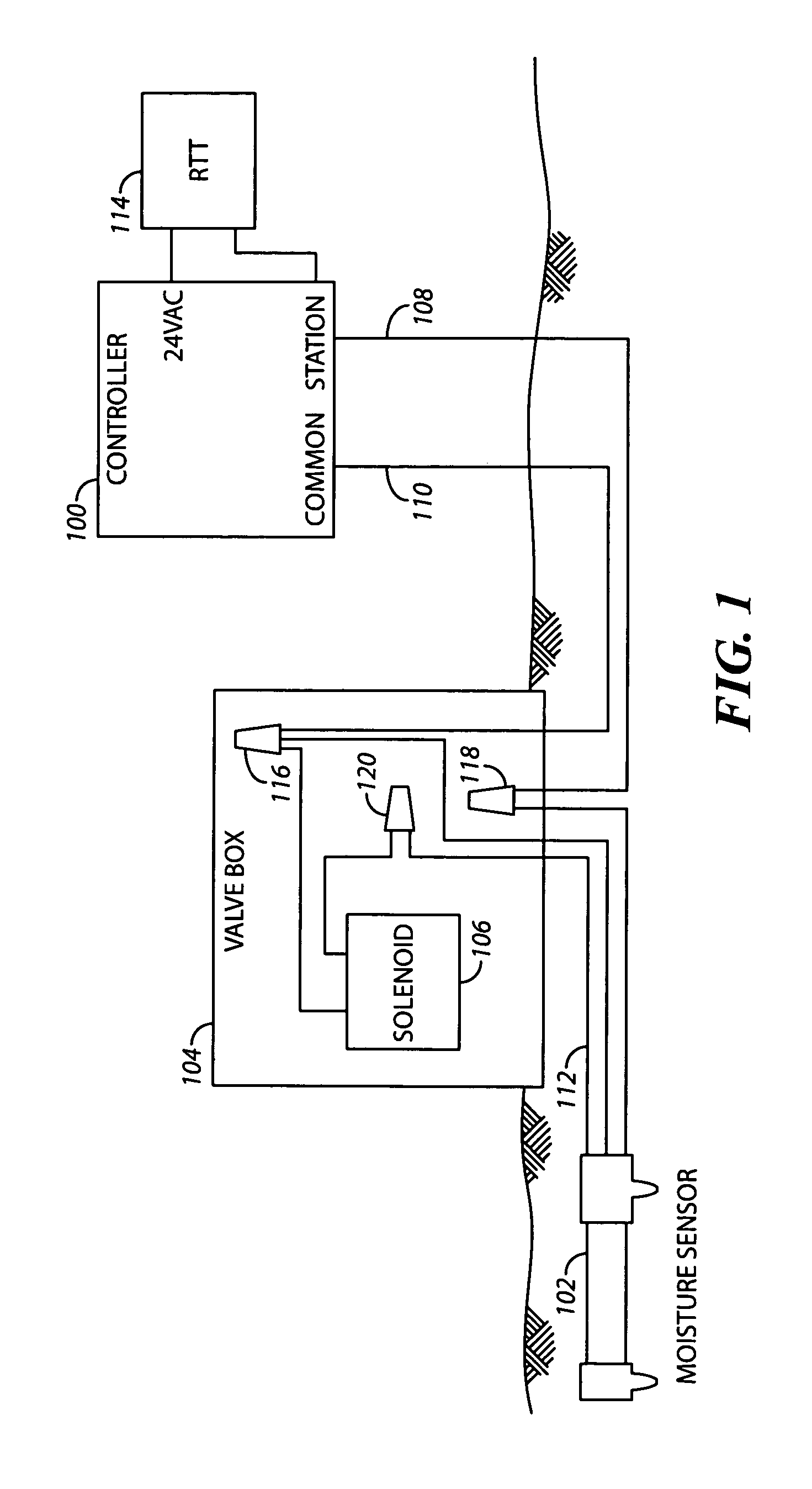
[0040]Referring to FIG. 1 a block diagram is shown illustrating an irrigation system in accordance with one embodiment. Shown is an irrigation controller 100, a sensor 102 (also referred to herein as a moisture sensor unit), a valve box 104, a solenoid valve 106 (also referred to as a valve), a power line 108, a common line 110, an actuation line 112, a remote test tool 114, a first connector 116, a second connector 118, and a third connector 120.

[0041]The valve box 104 houses the solenoid valve 106. As referred to herein the solenoid valve 106 is a valve that ...


PUM

PropertyMeasurementUnit
DC voltageaaaaaaaaaa
dielectric constantaaaaaaaaaa

Abstract

Moisture sensor devices and methods associated with operation of the moisture sensor devices are disclosed herein. One embodiment includes a moisture sensor and controller device adapted to be placed in soil comprising a switch adapted to be coupled to a power control line of an irrigation controller, the power control line for sending an activating power signal to an irrigation valve; a control circuit coupled to the switch; and a sensor circuit coupled to the control circuit and adapted to provide a signal to the control circuit, the signal corresponding to a moisture level of the soil; wherein the control circuit is adapted to control the switch to interrupt the activating power signal based on the signal from the sensor circuit; wherein the switch and the control circuit are both external to the irrigation controller.

Description

RELATED APPLICATIONS[0001]This application is a continuation-in-part of U.S. patent application Ser. No. 11 / 027,355, filed Dec. 29, 2004, entitled CAPACITANCE-BASED MOISTURE SENSOR AND CONTROLLER, to Dresselhaus et al., which application is incorporated herein by reference in its entirety.BACKGROUND OF THE INVENTION[0002]1. Field of the Invention[0003]The present invention relates to moisture sensors for use in irrigation. More specifically, the present invention relates to capacitance-based moisture sensors.[0004]2. Discussion of the Related Art[0005]Generally, in irrigation systems utilizing a moisture sensor, a moisture sensor is placed in the ground that outputs information about a moisture level of surrounding soil to an irrigation controller in a separate location. The irrigation controller is typically coupled to and controls multiple valves that control water flow to one or more sprinkler devices. The irrigation controller processes the information received from the sensor a...

Claims


Application Information

Patent Timeline
Patent Type & Authority Patents(United States)
IPC IPC(8): G05B11/00G01N25/56
CPCG01N27/223G01N33/246F16K37/0091Y10T137/189
Inventor DRESSELHAUS, DANIEL D.O'BRIEN, KEVIN G.
Owner RAIN BIRD CORP
Why Eureka
Try Eureka